This document is autogenerated from generate_ui_documentation.py. Do not edit this document directly.
Save Specification Saves specification data to a file.
Specification Channel Specifies which control channel to display on the Specification Plot.
Specification Plot This plot displays the specified SRS for the selected channel.
SDS Synthesize Brings up a dialog box to allow the user to investigate synthesizing ideal data that matches the specified SRS.
Control Channels Channels that are checked will be used as the control channels for this environment. The control channels should be ordered in the specification the same way they are ordered in this list. For example, the first SRS in the specification will correspond to the first checked channel in this list.
Check Selected When clicked, any selected channels in the Control Channels list will be checked, and therefore used as control channels in the environment.
Uncheck Selected When clicked, any selected channels in the Control Channels list will be unchecked, and therefore not used as control channels in the environment.
Input Channels A display showing the total number of physical channels this environment is measuring, including excitation channels and control channels.
Output Channels A display showing the total number of physical channels this environment is outputting to excitation devices such as vibration shakers.
Control Channels A display showing the total number of physical channels this environment is controlling to.
Transform Controls A display showing the number of virtual control channels in the environment due to transformation matrices applied to the physical control channels.
Transform Outputs A display showing the number of virtual excitation channels in the environment due to transformation matrices applied to the physical excitation channels.
Transformation Matrices... Open the transformation matrix dialog to allow specification of transformations to virtual control or virtual excitation channels.
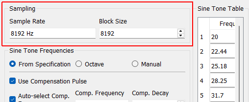
Sample Rate Sample rate in samples per second of the data acquisition hardware, for display only. This is a global parameter and must be set in the Data Acquisition Setup tab.
Block Size The length of the time signal in samples that will be generated. If this is too short for the specified decay, the signals will be truncated.
From Specification If selected, the sum of decayed sine signals generated will have a sine tone for each breakpoint in the specified shock response spectra.
Octave If selected, sine tones will be specified using a minimum frequency, maximum frequency, and number of sine tones per octave.
Manual If selected, the user can manually specify sine tone frequencies.
Use Compensation Pulse If selected, a compensation pulse will be utilized. The compensation pulse is often utilized by shock controllers to allow the shaker to return to zero displacement and velocity without a sharp pull-back at the end of the signal. How the compensation pulse is used (if at all) is determined by the control law specified.
Auto-select Compensation Frequency If selected, the frequency of the compensation pulse will be set to 1/3 of the frequency of the lowest sine tone.
Compensation Pulse Frequency Specifies the frequency used by the compensation pulse.
Compensation Decay Specifies the decay parameter used by the compensation pulse. This determines how quickly the compensation pulse decays.
Damping (Zeta) If this is selected, decay will be specified as a critical damping ratio (specified by the variable zeta in many formulas).
Time Constant (Tau) If this is selected, decay will be specified as a time constant (specified by the variable tau in many formulas). The time constant is time where the decay has reached 63.2% of the original value.
Number Time Constants If this is selected, decay will be specified as the number of time constants (specified by the variable tau in many formulas within the block. The time constant is time where the decay has reached 63.2% of the original value. The if the number of time constants is set to 5, the decay will be such that the time constant will be 1/5 of the the block size.
Common Decay for All Sine Tones If selected, all sine tones will have the same decay value. If not selected, each sine tone’s decay value can be specified individually.
SRS Type This specifies the type of SRS to compute. There are many different SRS types, including: Primary refers to the peak occuring during the pulse. Residual refers to the peak occuring after the input has ended. Positive, Negative, and Absolute Maximum refer to the maximum positive, maximum negative, and maximum absolute value of response. Primary Positive Largest positive response during input Primary Negative Largest negative response during input Primary Absolute Maximum Largest magnitude response during input Residual Positive Largest positive response after input ends Residual Negative Largest negative response after input ends Residual Absolute Maximum Largest magnitude response after input ends Maximum Positive Largest positive response over entire event Maximum Negative Largest negative response over entire event Maximum Absolute Maximum Largest magnitude response over entire event
Displacement This specifies what displacement type is measured by the SRS. Absolute displacement refers to the oscillator’s motion in inertial space. Relative displacement refers to the oscillator’s motion relative to its base motion.
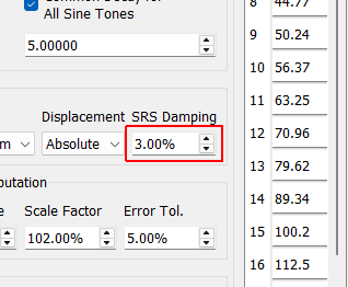
SRS Damping This is the fraction of critical damping applied to each single degree of freedom oscillator when computing the SRS.
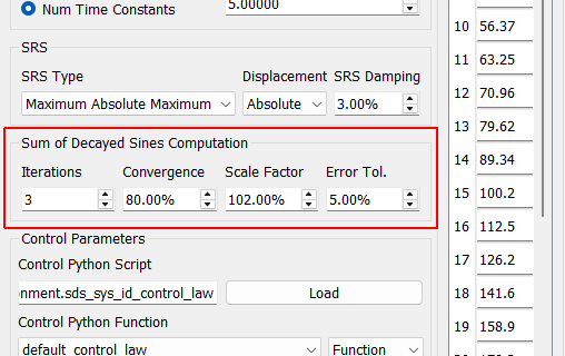
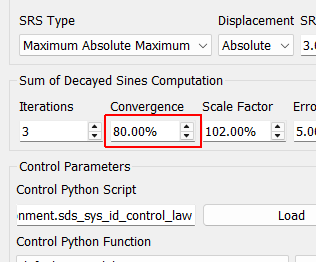
Convergence SRS are nonlinear functions, so an optimization routine is required to solve for sum of decayed sine amplitudes that match the SRS. The convergence parameter specifies how much change the optimizer is allowed to make at each step.
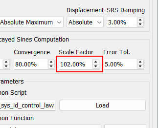
Scale Factor The scale factor is applied to the SRS to make the sum of decayed sines match the SRS better, rather than just touching it at the sine tones.
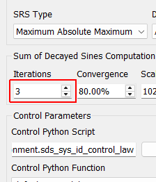
Iterations SRS are nonlinear functions, so an optimization routine is required to solve for sum of decayed sine amplitudes that match the SRS. This value specifies the number of optimization routines to use.
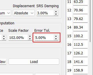
Error Tolerance This is the allowable error in the optimization.
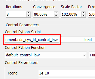
Control Python Script Python script used to specify the control law.
Load Opens a file dialog to load in a Python script containing the control law.
Control Python Function Selects the function or class in the Python script to use as the control law.
Control Type Select if the selected control law is a Function, Class, or Interactive Class. This should be detected automatically by inspection; users should not have to adjust this.
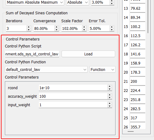
Control Parameters Any additional parameters needed by the control law are entered in this area. This area will be automatically populated based on the extra arguments required by the control law.
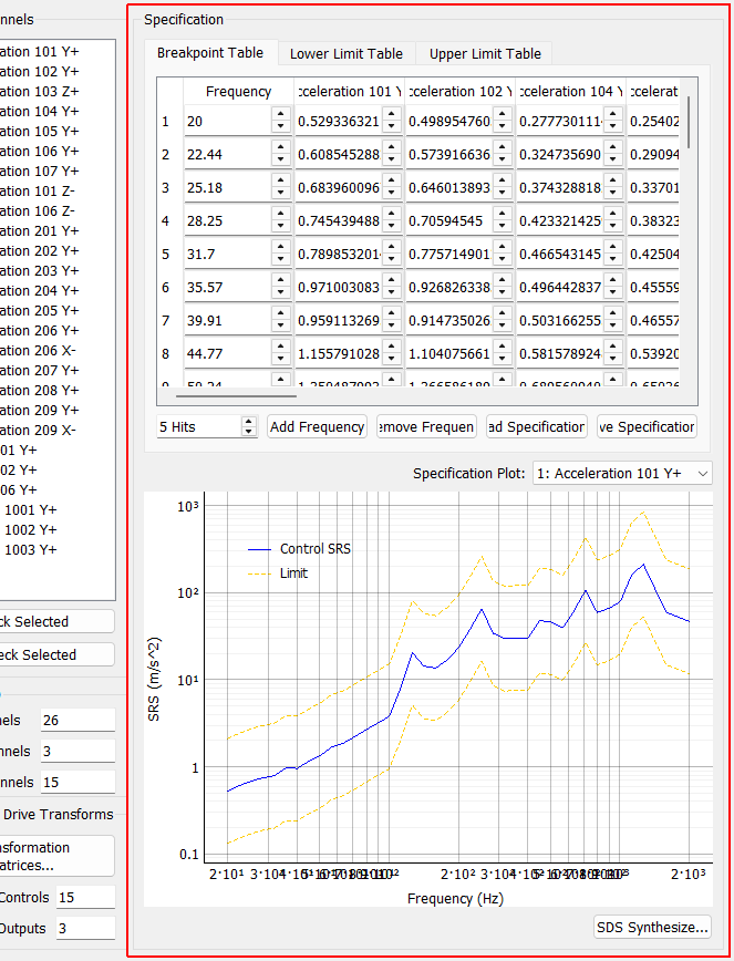
Specification
Save Specification Saves specification data to a file.
Specification Channel Specifies which control channel to display on the Specification Plot.
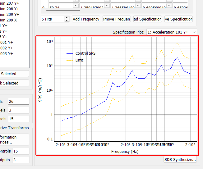
Specification Plot This plot displays the specified SRS for the selected channel.
SDS Synthesize Brings up a dialog box to allow the user to investigate synthesizing ideal data that matches the specified SRS.
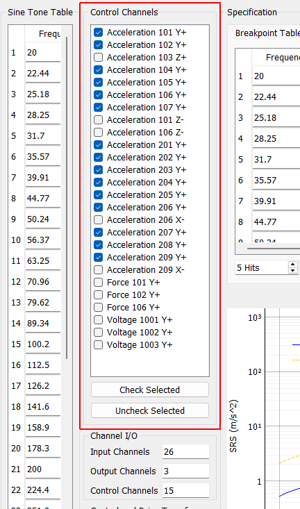
Control Channels
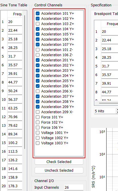
Control Channels Channels that are checked will be used as the control channels for this environment. The control channels should be ordered in the specification the same way they are ordered in this list. For example, the first SRS in the specification will correspond to the first checked channel in this list.
Check Selected When clicked, any selected channels in the Control Channels list will be checked, and therefore used as control channels in the environment.
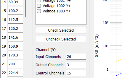
Uncheck Selected When clicked, any selected channels in the Control Channels list will be unchecked, and therefore not used as control channels in the environment.
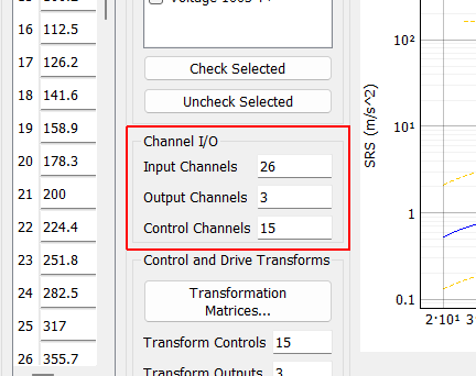
Channel I/O
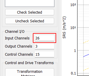
Input Channels A display showing the total number of physical channels this environment is measuring, including excitation channels and control channels.
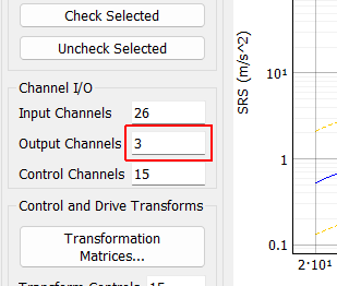
Output Channels A display showing the total number of physical channels this environment is outputting to excitation devices such as vibration shakers.
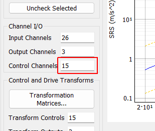
Control Channels A display showing the total number of physical channels this environment is controlling to.
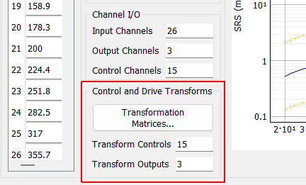
Control and Drive Transforms
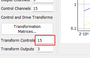
Transform Controls A display showing the number of virtual control channels in the environment due to transformation matrices applied to the physical control channels.
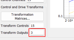
Transform Outputs A display showing the number of virtual excitation channels in the environment due to transformation matrices applied to the physical excitation channels.
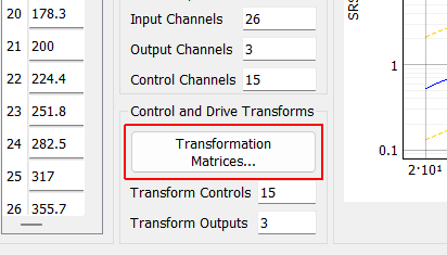
Transformation Matrices... Open the transformation matrix dialog to allow specification of transformations to virtual control or virtual excitation channels.
Sine Tone Table
Sampling
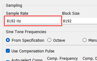
Sample Rate Sample rate in samples per second of the data acquisition hardware, for display only. This is a global parameter and must be set in the Data Acquisition Setup tab.
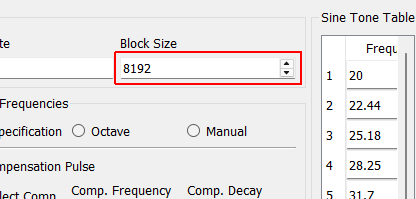
Block Size The length of the time signal in samples that will be generated. If this is too short for the specified decay, the signals will be truncated.
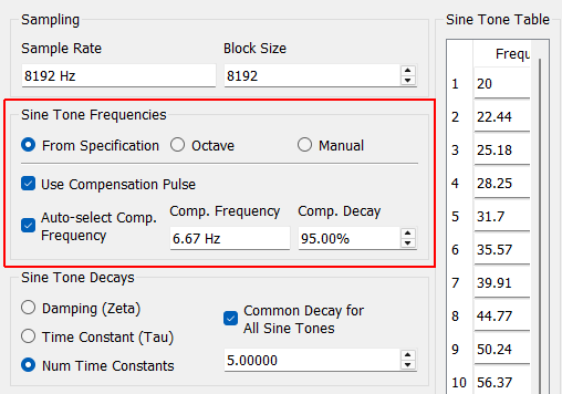
Sine Tone Frequencies
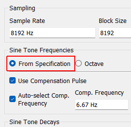
From Specification If selected, the sum of decayed sine signals generated will have a sine tone for each breakpoint in the specified shock response spectra.
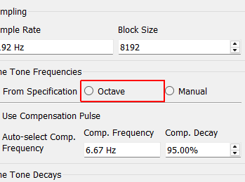
Octave If selected, sine tones will be specified using a minimum frequency, maximum frequency, and number of sine tones per octave.
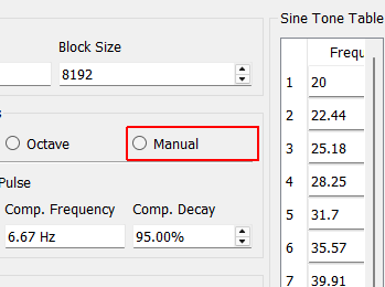
Manual If selected, the user can manually specify sine tone frequencies.
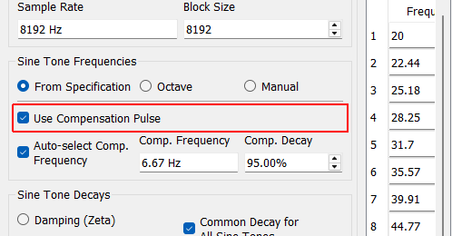
Use Compensation Pulse If selected, a compensation pulse will be utilized. The compensation pulse is often utilized by shock controllers to allow the shaker to return to zero displacement and velocity without a sharp pull-back at the end of the signal. How the compensation pulse is used (if at all) is determined by the control law specified.
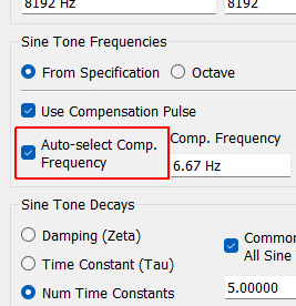
Auto-select Compensation Frequency If selected, the frequency of the compensation pulse will be set to 1/3 of the frequency of the lowest sine tone.
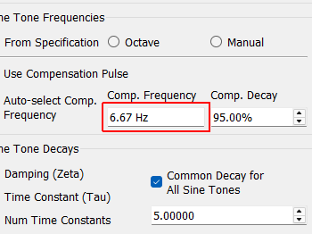
Compensation Pulse Frequency Specifies the frequency used by the compensation pulse.
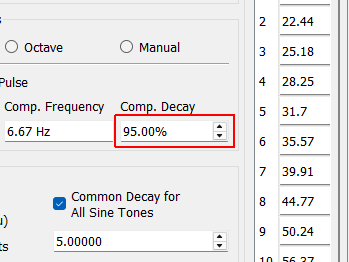
Compensation Decay Specifies the decay parameter used by the compensation pulse. This determines how quickly the compensation pulse decays.
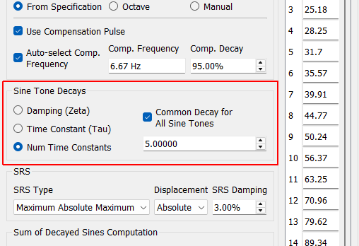
Sine Tone Decays
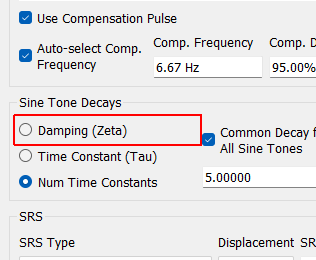
Damping (Zeta) If this is selected, decay will be specified as a critical damping ratio (specified by the variable zeta in many formulas).
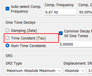
Time Constant (Tau) If this is selected, decay will be specified as a time constant (specified by the variable tau in many formulas). The time constant is time where the decay has reached 63.2% of the original value.
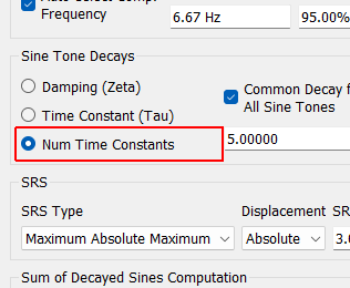
Number Time Constants If this is selected, decay will be specified as the number of time constants (specified by the variable tau in many formulas within the block. The time constant is time where the decay has reached 63.2% of the original value. The if the number of time constants is set to 5, the decay will be such that the time constant will be 1/5 of the the block size.
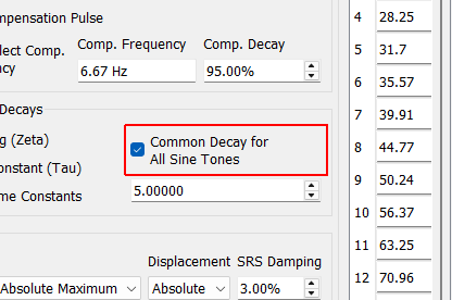
Common Decay for All Sine Tones If selected, all sine tones will have the same decay value. If not selected, each sine tone’s decay value can be specified individually.
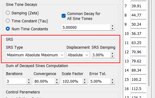
SRS

SRS Type This specifies the type of SRS to compute. There are many different SRS types, including: Primary refers to the peak occuring during the pulse. Residual refers to the peak occuring after the input has ended. Positive, Negative, and Absolute Maximum refer to the maximum positive, maximum negative, and maximum absolute value of response. Primary Positive Largest positive response during input Primary Negative Largest negative response during input Primary Absolute Maximum Largest magnitude response during input Residual Positive Largest positive response after input ends Residual Negative Largest negative response after input ends Residual Absolute Maximum Largest magnitude response after input ends Maximum Positive Largest positive response over entire event Maximum Negative Largest negative response over entire event Maximum Absolute Maximum Largest magnitude response over entire event
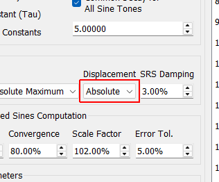
Displacement This specifies what displacement type is measured by the SRS. Absolute displacement refers to the oscillator’s motion in inertial space. Relative displacement refers to the oscillator’s motion relative to its base motion.
SRS Damping This is the fraction of critical damping applied to each single degree of freedom oscillator when computing the SRS.
Sum of Decayed Sines Computation
Convergence SRS are nonlinear functions, so an optimization routine is required to solve for sum of decayed sine amplitudes that match the SRS. The convergence parameter specifies how much change the optimizer is allowed to make at each step.
Scale Factor The scale factor is applied to the SRS to make the sum of decayed sines match the SRS better, rather than just touching it at the sine tones.
Iterations SRS are nonlinear functions, so an optimization routine is required to solve for sum of decayed sine amplitudes that match the SRS. This value specifies the number of optimization routines to use.
Error Tolerance This is the allowable error in the optimization.
Control Parameters
Control Python Script Python script used to specify the control law.
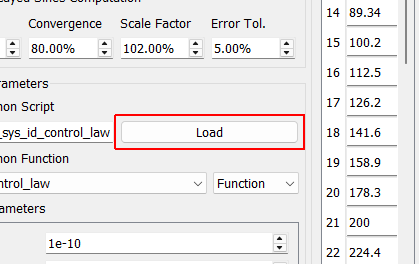
Load Opens a file dialog to load in a Python script containing the control law.
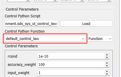
Control Python Function Selects the function or class in the Python script to use as the control law.
Control Type Select if the selected control law is a Function, Class, or Interactive Class. This should be detected automatically by inspection; users should not have to adjust this.
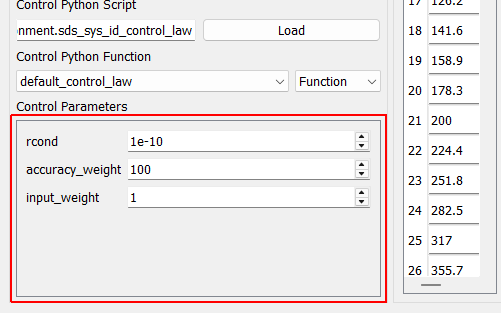
Control Parameters Any additional parameters needed by the control law are entered in this area. This area will be automatically populated based on the extra arguments required by the control law.
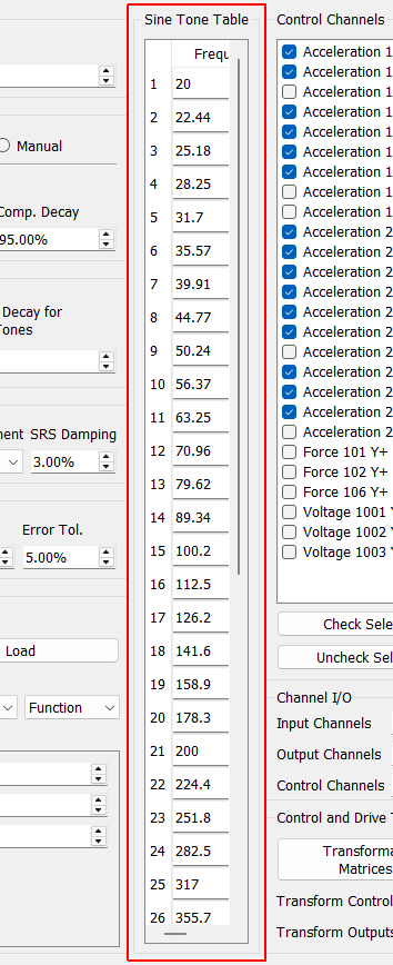
Sine Tone Table The sine tones and decay values used in the test are listed here. If sine tone frequencies or decay values are specified manually, they can be set in this table.
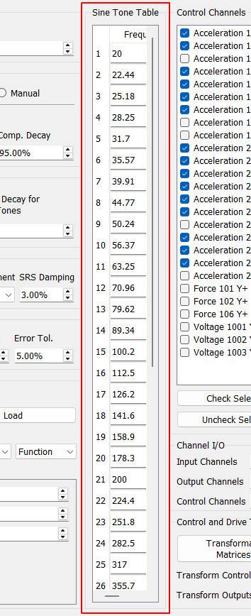
Sine Tone Table
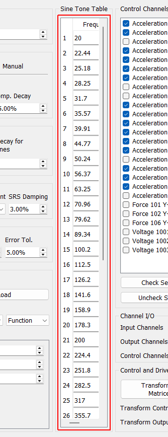
Sine Tone Table The sine tones and decay values used in the test are listed here. If sine tone frequencies or decay values are specified manually, they can be set in this table.
Maximum Frequency This sets the maximum sine tone frequency when specifying sine tones by octave.
Minimum Frequency This sets the minimum sine tone frequency when specifying sine tones by octave.
Tones per Octave This specifies the number of sine tones per octave when sine tones are specified by octave. Each octave is a doubling of the frequency, so sine tones will be logarithmically spaced with the number of tones specified occuring between each doubling of the frequency.
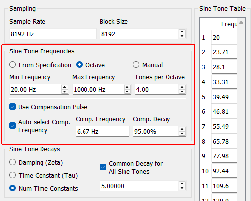
Sine Tone Frequencies
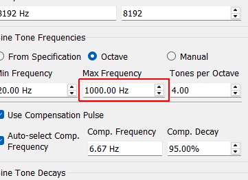
Maximum Frequency This sets the maximum sine tone frequency when specifying sine tones by octave.
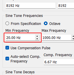
Minimum Frequency This sets the minimum sine tone frequency when specifying sine tones by octave.
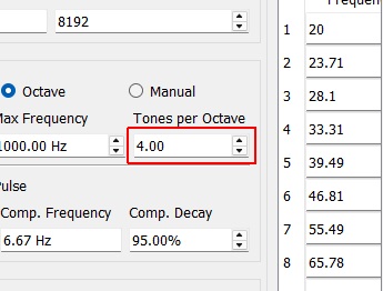
Tones per Octave This specifies the number of sine tones per octave when sine tones are specified by octave. Each octave is a doubling of the frequency, so sine tones will be logarithmically spaced with the number of tones specified occuring between each doubling of the frequency.
Sine Tone Table The sine tones and decay values used in the test are listed here. If sine tone frequencies or decay values are specified manually, they can be set in this table.
Add Tone Adds a sine tone to the sine tone table.
Remove Tone Removes the selected sine tone from the table.
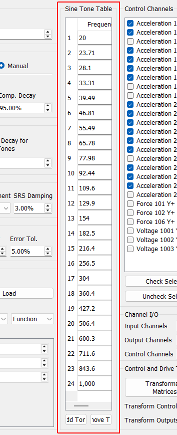
Sine Tone Table
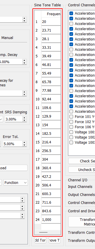
Sine Tone Table The sine tones and decay values used in the test are listed here. If sine tone frequencies or decay values are specified manually, they can be set in this table.
Add Tone Adds a sine tone to the sine tone table.
Remove Tone Removes the selected sine tone from the table.
Decay Value This is the numerical value used to specify the damping. The meaning of this value will depend on the type of decay selected (Damping, Time Constant, or Num Time Constants).
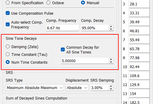
Sine Tone Decays
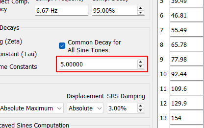
Decay Value This is the numerical value used to specify the damping. The meaning of this value will depend on the type of decay selected (Damping, Time Constant, or Num Time Constants).
Sine Tone Table The sine tones and decay values used in the test are listed here. If sine tone frequencies or decay values are specified manually, they can be set in this table.
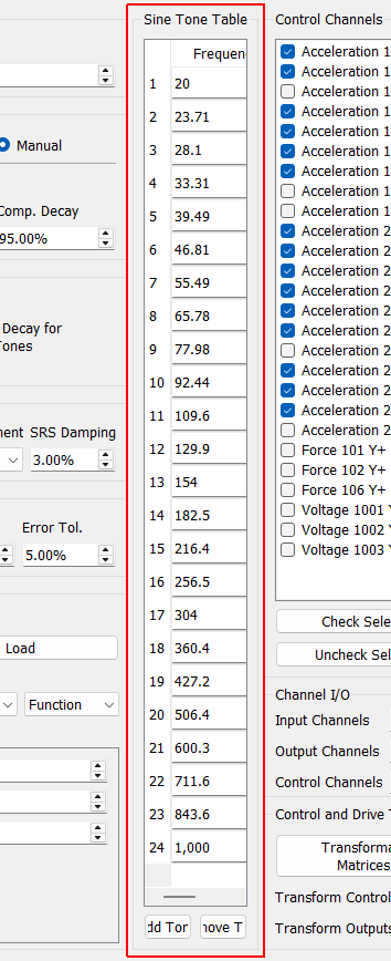
Sine Tone Table
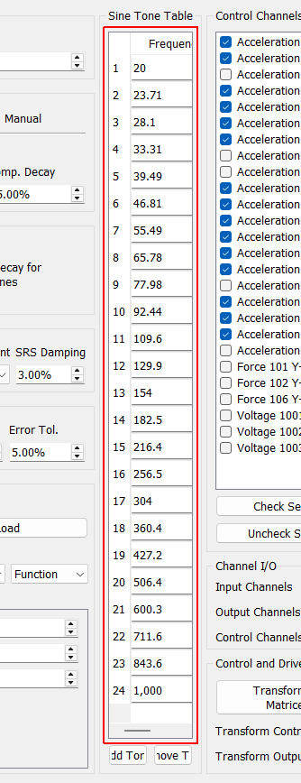
Sine Tone Table The sine tones and decay values used in the test are listed here. If sine tone frequencies or decay values are specified manually, they can be set in this table.
Breakpoint Table This table includes frequency breakpoints and SRS values for the specification.
Add Frequency Adds a frequency breakpoint to the specification table.
Remove Frequency Removes the selected frequency breakpoint from the specification table.
Load Specification Loads specification data from a file.
Number of Hits Specifies the number of hits at full level that should be applied to the test article.
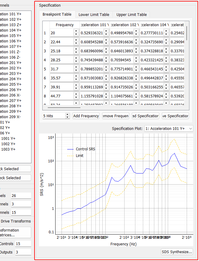
Specification
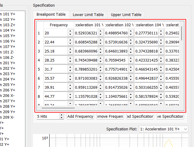
Breakpoint Table This table includes frequency breakpoints and SRS values for the specification.
Add Frequency Adds a frequency breakpoint to the specification table.
Remove Frequency Removes the selected frequency breakpoint from the specification table.
Load Specification Loads specification data from a file.
Number of Hits Specifies the number of hits at full level that should be applied to the test article.
Lower Limit Table This table specifies lower SRS limits at each breakpoint frequency.
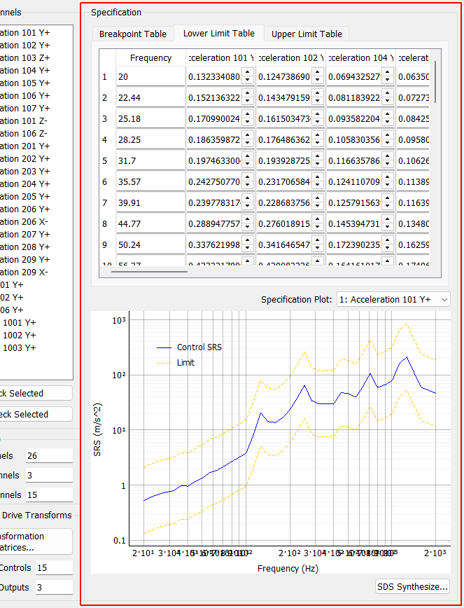
Specification
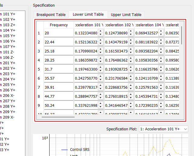
Lower Limit Table This table specifies lower SRS limits at each breakpoint frequency.
Upper Limit Table This table specifies upper SRS limits at each breakpoint frequency.
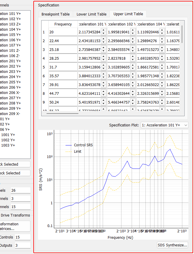
Specification
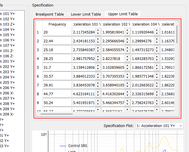
Upper Limit Table This table specifies upper SRS limits at each breakpoint frequency.