This document is autogenerated from generate_ui_documentation.py. Do not edit this document directly.
Samples per Acquire Number of samples that the control process processes at a time. This will be equal to the Samples per Frame * (1 - Overlap Percentage / 100). This need not correspond to the read or write size of the data acquisition system as the control process acquisition is buffered.
Sample Rate Sample rate in samples per second of the data acquisition hardware, for display only. This is a global parameter and must be set in the Data Acquisition Setup tab.
Nyquist Frequency The Nyquist Frequency is the highest frequency that can be analyzed using frequency domain techniques. It is the Sample Rate / 2.
FFT Lines The number of frequency lines in the Fast Fourier Transform output, which is the number of frequency lines that will be in the Transfer Function and CPSD matrices.
Frequency Spacing The frequency resolution of the measurement, computed by 1/Frame Time.
Samples per Frame Samples per measurement frame in the controller. The measurement frame is the “block” of data upon which the signal processing will be performed. This value will determine the window size. A larger value will result in more frequency lines in the FFT analysis. This need not correspond to the read or write size in the data acquisition system.
Frame Time Time to acquire each measurement frame in seconds. This is the Samples per Frame divided by the Sample Rate.
Averaging Type Specifies how averaging is performed. Linear averaging weights all measurement frames equally. Exponential averaging weights more recent frames more heavily.
Overlap Percentage The percentage overlap used between measurement frames. A 25% overlap means the last quarter of the previous measurement frame is used as the first quarter of the new measurement frame.
Averaging Coefficient Weighting applied to the most recent average when Exponential Averaging is used
FRF Technique Technique to compute the Transfer Function. H1 averages noise on the response channels.
Number of Averages The number of averages used to compute the frequency response functions.
FRF Window The window function applied to the measurement frames when computing the transfer functions. Rectangle: No window is used, all samples are weighted equally. Used for periodic signals or signals that start and end at zero in the measurement frame. Hann: Window that weights the start and end of the frame to zero and the middle to one. Useful for Random excitation to reduce leakage. Exponential: Window that weights the beginning of the frame more heavily than the end of the frame. Useful for impact testing where the test article’s response doesn’t decay by itself by the end of the measurement frame.
Window value at frame end Value of the exponential window at the end of the measurement frame, which is used to specify how quickly the exponential window decays.
Hysteresis Samples Number of samples that the trigger channel must be below the Hysteresis level. This property is read only and shown for the user’s convenience.
Pretrigger Amount of time in the measurement frame before the trigger occurs. The system retains a running buffer of recently acquired data looking for the trigger. When the trigger is found, the specified percentage of the frame is data that occured before the trigger. This is used to capture, for example, the entire transient of a shock, some of which may occur before the trigger depending on the trigger level.
Trigger Channel Select the channel to use as a trigger.
Wait for Steady State Amount of time to wait for the measurement to achieve a steady state response prior to performing signal processing operations.
Trigger Level (V) Level to trigger at in volts. This property is read only and displayed for the user’s convenience.
Triggering Type Type of trigger used for the analysis. Free Run: No triggering is used. First Frame: Triggering only starts the first measurement frame and then the measurement proceeds as if it were a Free Run. Every Frame: The measurement waits for a trigger for every measurement frame.
Acceptance Determines how measurement frames are accepted or rejected. Accept All: Accepts all measurement frames Manual: Allows the user to specify whether the recently obtained measurement frame should be accepted or rejected. Autoreject...: Allows the user to load in a Python function to automatically accept or reject the measurement frame based off of arbitrary criteria.
Trigger Level Level to trigger at as a percentage of the range of the channel.
Trigger Level (EU) Level to trigger at in Engineering Units. This property is read only and displayed for the user’s convenience.
Hysteresis Level Level that the signal must return to prior to a new trigger being able to be accepted. This ensures that the system must return to some nominal state prior to a new trigger being obtained. Specified in percentage of the range of the channel.
Hysteresis Level (V) Level that the trigger channel must fall below to achieve a subsequent trigger in volts. This property is read only and displayed for the user’s convenience.
Hysteresis Level (EU) Level that the trigger channel must fall below to achieve a subsequent trigger in Engineering Units. This property is read only and displayed for the user’s convenience.
Trigger Slope Slope of the trigger. If the slope is Positive, it will look for a rising signal to trigger the measurement. If the trigger slope is Negative, it will look for a falling signal to trigger the measurement.
Hysteresis Time (s) Amount of time that the trigger channel must be below the Hysteresis level. This property is read only and is displayed for the user’s convenience.
Hysteresis Frame % Percentage of the measurement frame that the signal must be below the Hysteresis value in order to accept a new trigger. Useful for Burst Random excitation where you don’t want to accidentally trigger midway through the burst.
Reference Channels Number of reference channels used to compute frequency response function
Output Channels Number of excitation channels in the current test.
Response Channels Number of response channels used when computing frequency response functions.
Channel Selection Table By checking the box in the Reference column, a channel can be made into a reference channel rather than a response channel. Unchecking the box in the Enabled column with disable the channel. Disabling an excitation channel will disable that excitation device. Disabling a reference will remove that reference from the FRF computation.
Disable Selected Disables the currently selected channels in the Channel Selections table
Enable Selected Enables the channels currently selected in the Channel Selections table
Check Selected References Turns the selected channels into reference channels for computing FRFs
Uncheck Selected References Turns the selected channels into response channels for computing FRFs
Signal Generation Tabs Switching tabs will change the type of excitation signal that will be output.
Output Signal Realization of the signals that will be generated. Note that for random signals, the actual signal may vary slightly from this representation, as the generation of those signals is random.
Automatically Regenerate Signal on Parameter Change Check to automatically regenerate signals when signal generation parameters are updated. If not checked, you will need to click the
Regenerate Signalsbutton to see changes.Regenerate Signal Generate a new realization of the output signals.
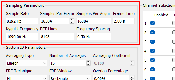
Sampling Parameters
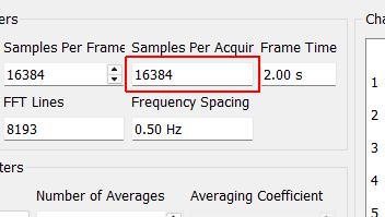
Samples per Acquire Number of samples that the control process processes at a time. This will be equal to the Samples per Frame * (1 - Overlap Percentage / 100). This need not correspond to the read or write size of the data acquisition system as the control process acquisition is buffered.
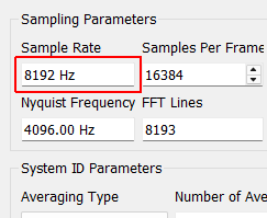
Sample Rate Sample rate in samples per second of the data acquisition hardware, for display only. This is a global parameter and must be set in the Data Acquisition Setup tab.
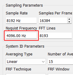
Nyquist Frequency The Nyquist Frequency is the highest frequency that can be analyzed using frequency domain techniques. It is the Sample Rate / 2.
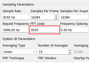
FFT Lines The number of frequency lines in the Fast Fourier Transform output, which is the number of frequency lines that will be in the Transfer Function and CPSD matrices.
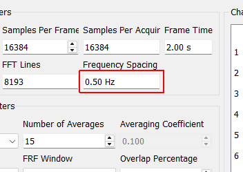
Frequency Spacing The frequency resolution of the measurement, computed by 1/Frame Time.
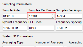
Samples per Frame Samples per measurement frame in the controller. The measurement frame is the “block” of data upon which the signal processing will be performed. This value will determine the window size. A larger value will result in more frequency lines in the FFT analysis. This need not correspond to the read or write size in the data acquisition system.
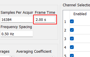
Frame Time Time to acquire each measurement frame in seconds. This is the Samples per Frame divided by the Sample Rate.
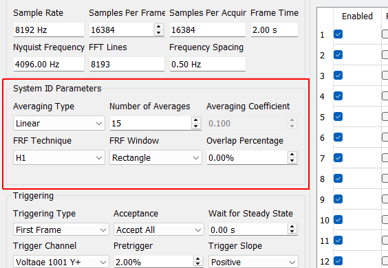
System ID Parameters
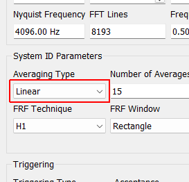
Averaging Type Specifies how averaging is performed. Linear averaging weights all measurement frames equally. Exponential averaging weights more recent frames more heavily.
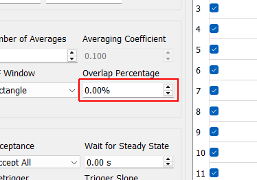
Overlap Percentage The percentage overlap used between measurement frames. A 25% overlap means the last quarter of the previous measurement frame is used as the first quarter of the new measurement frame.
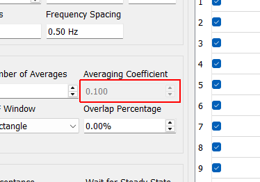
Averaging Coefficient Weighting applied to the most recent average when Exponential Averaging is used
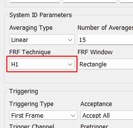
FRF Technique Technique to compute the Transfer Function. H1 averages noise on the response channels.
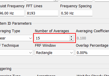
Number of Averages The number of averages used to compute the frequency response functions.
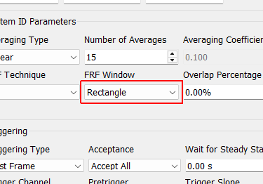
FRF Window The window function applied to the measurement frames when computing the transfer functions. Rectangle: No window is used, all samples are weighted equally. Used for periodic signals or signals that start and end at zero in the measurement frame. Hann: Window that weights the start and end of the frame to zero and the middle to one. Useful for Random excitation to reduce leakage. Exponential: Window that weights the beginning of the frame more heavily than the end of the frame. Useful for impact testing where the test article’s response doesn’t decay by itself by the end of the measurement frame.
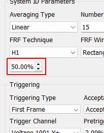
Window value at frame end Value of the exponential window at the end of the measurement frame, which is used to specify how quickly the exponential window decays.
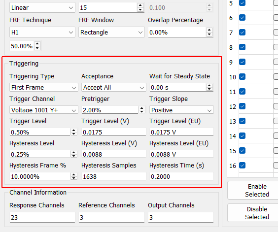
Triggering
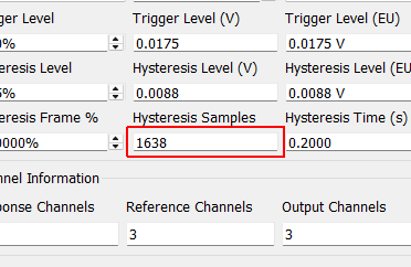
Hysteresis Samples Number of samples that the trigger channel must be below the Hysteresis level. This property is read only and shown for the user’s convenience.
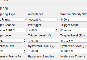
Pretrigger Amount of time in the measurement frame before the trigger occurs. The system retains a running buffer of recently acquired data looking for the trigger. When the trigger is found, the specified percentage of the frame is data that occured before the trigger. This is used to capture, for example, the entire transient of a shock, some of which may occur before the trigger depending on the trigger level.
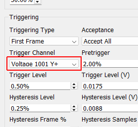
Trigger Channel Select the channel to use as a trigger.
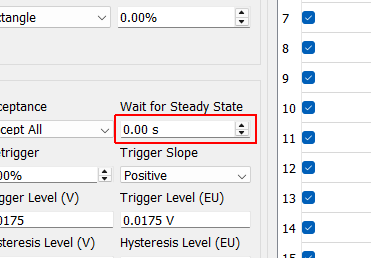
Wait for Steady State Amount of time to wait for the measurement to achieve a steady state response prior to performing signal processing operations.
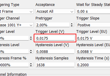
Trigger Level (V) Level to trigger at in volts. This property is read only and displayed for the user’s convenience.
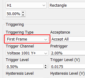
Triggering Type Type of trigger used for the analysis. Free Run: No triggering is used. First Frame: Triggering only starts the first measurement frame and then the measurement proceeds as if it were a Free Run. Every Frame: The measurement waits for a trigger for every measurement frame.
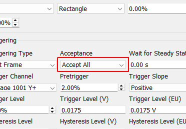
Acceptance Determines how measurement frames are accepted or rejected. Accept All: Accepts all measurement frames Manual: Allows the user to specify whether the recently obtained measurement frame should be accepted or rejected. Autoreject...: Allows the user to load in a Python function to automatically accept or reject the measurement frame based off of arbitrary criteria.
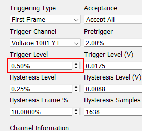
Trigger Level Level to trigger at as a percentage of the range of the channel.
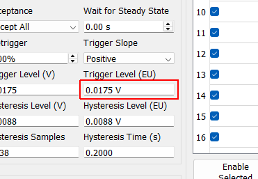
Trigger Level (EU) Level to trigger at in Engineering Units. This property is read only and displayed for the user’s convenience.
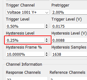
Hysteresis Level Level that the signal must return to prior to a new trigger being able to be accepted. This ensures that the system must return to some nominal state prior to a new trigger being obtained. Specified in percentage of the range of the channel.
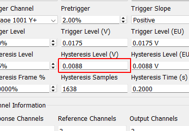
Hysteresis Level (V) Level that the trigger channel must fall below to achieve a subsequent trigger in volts. This property is read only and displayed for the user’s convenience.
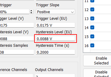
Hysteresis Level (EU) Level that the trigger channel must fall below to achieve a subsequent trigger in Engineering Units. This property is read only and displayed for the user’s convenience.
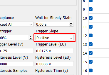
Trigger Slope Slope of the trigger. If the slope is Positive, it will look for a rising signal to trigger the measurement. If the trigger slope is Negative, it will look for a falling signal to trigger the measurement.
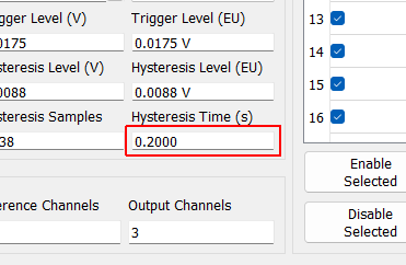
Hysteresis Time (s) Amount of time that the trigger channel must be below the Hysteresis level. This property is read only and is displayed for the user’s convenience.
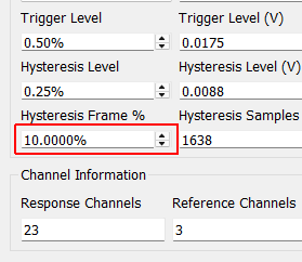
Hysteresis Frame % Percentage of the measurement frame that the signal must be below the Hysteresis value in order to accept a new trigger. Useful for Burst Random excitation where you don’t want to accidentally trigger midway through the burst.
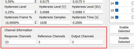
Channel Information
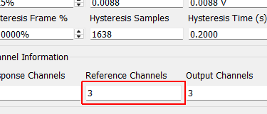
Reference Channels Number of reference channels used to compute frequency response function
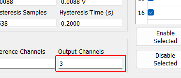
Output Channels Number of excitation channels in the current test.
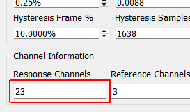
Response Channels Number of response channels used when computing frequency response functions.
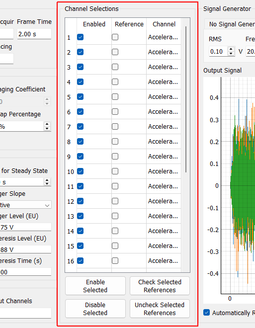
Channel Selections
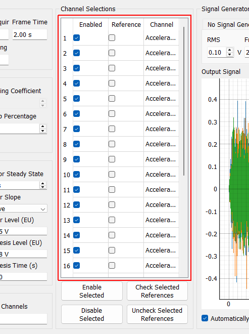
Channel Selection Table By checking the box in the Reference column, a channel can be made into a reference channel rather than a response channel. Unchecking the box in the Enabled column with disable the channel. Disabling an excitation channel will disable that excitation device. Disabling a reference will remove that reference from the FRF computation.
Disable Selected Disables the currently selected channels in the Channel Selections table
Enable Selected Enables the channels currently selected in the Channel Selections table
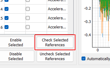
Check Selected References Turns the selected channels into reference channels for computing FRFs
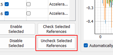
Uncheck Selected References Turns the selected channels into response channels for computing FRFs
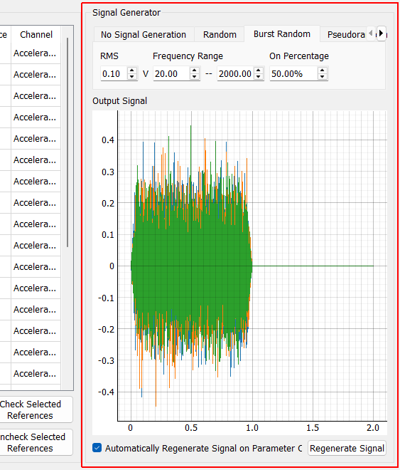
Signal Generator
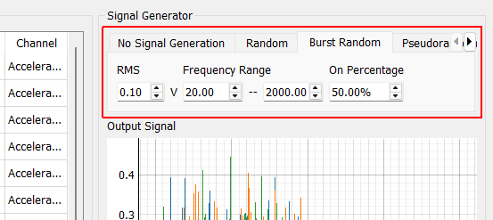
Signal Generation Tabs Switching tabs will change the type of excitation signal that will be output.
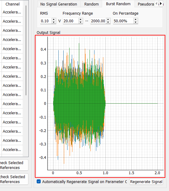
Output Signal Realization of the signals that will be generated. Note that for random signals, the actual signal may vary slightly from this representation, as the generation of those signals is random.
Automatically Regenerate Signal on Parameter Change Check to automatically regenerate signals when signal generation parameters are updated. If not checked, you will need to click the Regenerate Signals button to see changes.
Regenerate Signal Generate a new realization of the output signals.
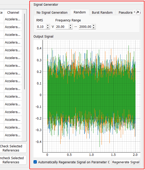
Random RMS RMS voltage level of the Random signal
Random Minimum Frequency Minimum frequency cutoff for the random vibration signal.
Random Maximum Frequency Maximum frequency cutoff for the random vibration signal.
Signal Generator
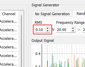
Random RMS RMS voltage level of the Random signal
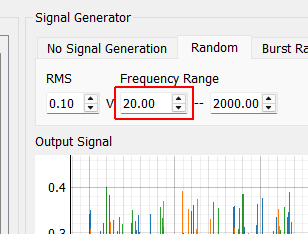
Random Minimum Frequency Minimum frequency cutoff for the random vibration signal.
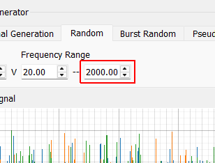
Random Maximum Frequency Maximum frequency cutoff for the random vibration signal.
Burst Random RMS RMS voltage of the burst portion of the excitation
Burst Random Minimum Frequency Minimum frequency of the burst excitation
Burst Random Maximum Frequency Maximum frequency of the burst excitation.
Burst Random On Percentage Percentage of the measurement frame that the burst is active for.
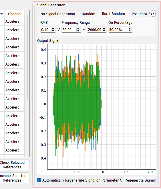
Signal Generator
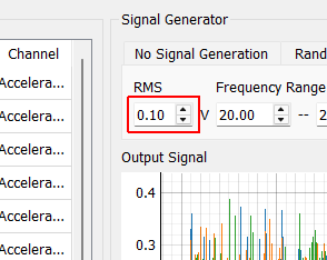
Burst Random RMS RMS voltage of the burst portion of the excitation
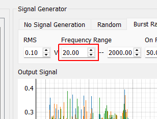
Burst Random Minimum Frequency Minimum frequency of the burst excitation
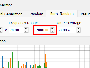
Burst Random Maximum Frequency Maximum frequency of the burst excitation.
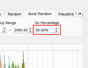
Burst Random On Percentage Percentage of the measurement frame that the burst is active for.
Pseudorandom RMS RMS voltage of the pseudorandom excitation
Pseudorandom Minimum Frequency Minimum frequency of the pseudorandom excitation
Pseudorandom Maximum Frequency Maximum frequency of the pseudorandom excitation.
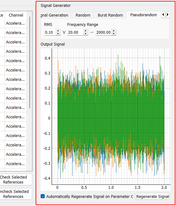
Signal Generator
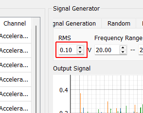
Pseudorandom RMS RMS voltage of the pseudorandom excitation
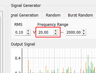
Pseudorandom Minimum Frequency Minimum frequency of the pseudorandom excitation
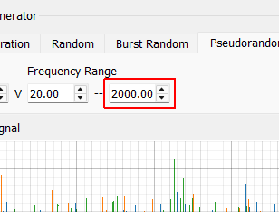
Pseudorandom Maximum Frequency Maximum frequency of the pseudorandom excitation.
Chirp Peak Level Peak level of the chirp signal
Chirp Minimum Frequency Starting frequency of the chirp
Chirp Maximum Frequency Ending frequency of the chirp
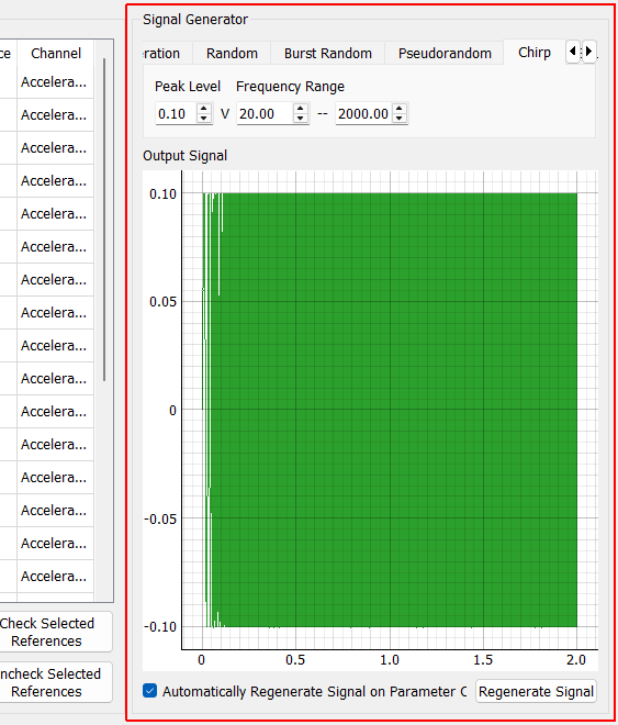
Signal Generator
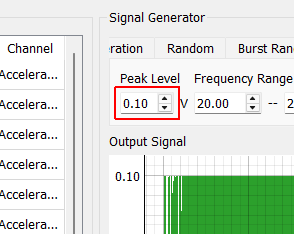
Chirp Peak Level Peak level of the chirp signal
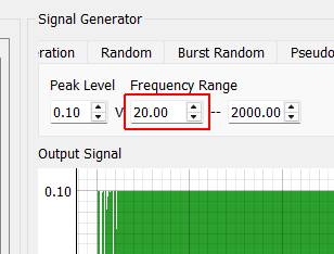
Chirp Minimum Frequency Starting frequency of the chirp
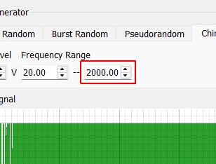
Chirp Maximum Frequency Ending frequency of the chirp
Square Wave Peak Level Amplitude of the square pulse
Square Wave Frequency Frequency of the square pulse
Square Wave Percent On Percentage of the square pulse’s period that it is “up”.
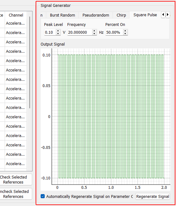
Signal Generator
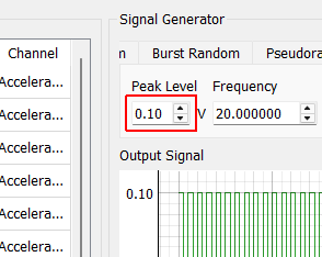
Square Wave Peak Level Amplitude of the square pulse
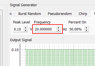
Square Wave Frequency Frequency of the square pulse
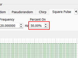
Square Wave Percent On Percentage of the square pulse’s period that it is “up”.
Sine Wave Peak Level Amplitude of the sinusoidal excitation
Sine Wave Frequency Frequency of the sinusoidal excitation
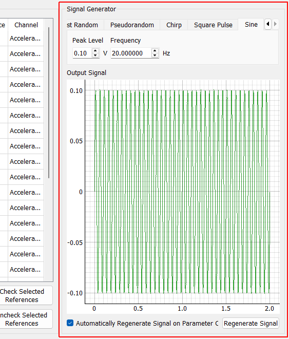
Signal Generator
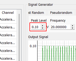
Sine Wave Peak Level Amplitude of the sinusoidal excitation
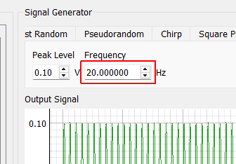
Sine Wave Frequency Frequency of the sinusoidal excitation