This document is autogenerated from generate_ui_documentation.py. Do not edit this document directly.
Sample Rate Sample rate in samples per second of the data acquisition hardware. This is a global parameter and must be set in the Data Acquisition Setup tab.
Samples Per Acquire Number of samples that the control process processes at a time. This is driven by the Rattlesnake read buffer size from the data acquisition parameters.
Acquire Time Time to acquire each acquisition chunk in seconds. This is the Samples per Acquire divided by the Sample Rate.
Nyquist Frequency The Nyquist Frequency is the highest frequency that can be analyzed using frequency domain techniques. It is the Sample Rate / 2.
Samples per Output Number of new samples generated by each realization taking into account the overlap with the previous realization.
Test Start/Stop Ramp Time Time in seconds that the controller takes to change the test level to or from zero. The test level is changed smoothly to prevent damaging the excitation hardware or part under test. Larger numbers will result in a more smooth transition between test levels, while smaller numbers will make the test level change more quickly.
Buffer Blocks The number of blocks to keep in the signal generation buffer. A smaller number will make the controller more responsive but also increase the risk of underflow issues which will stop the test abruptly and may damage test hardware.
Filter Type The type of filter used to extract the sinusoidal components from the running time data. The Digital Tracking Filter is a less computationally intensive filter, but can struggle to reject noise, other environments, or multiple sine tones. The Overlapped Vold-Kalman filter will do a better job rejecting noise and other environments, and can seamlessly handle multiple overlapping sine tones if they are all defined in this environment. For large tests, the Overlapped Vold-Kalman filter may not be able to be run real-time, which can cause underflow issues as the controller is waiting for its next control decision. It is highly recommended that users use the Explore... button to carefully evaluate their filter parameters and computational complexity!
Explore... Bring up a dialog box allowing the user to explore filter settings for their given test. The user should have their specifications defined prior to clicking this button to ensure filter exploration is performed on the most realistic dataset.
Control Channels A display showing the total number of physical channels this environment is controlling to.
Control Python Script Python script used to specify the control law.
Load Opens a file dialog to load in a Python script containing the control law.
Output Channels A display showing the total number of physical channels this environment is outputting to excitation devices such as vibration shakers.
Input Channels A display showing the total number of physical channels this environment is measuring, including excitation channels and control channels.
Control Python Class Selects the class in the Python script to use as the control law.
Custom Control Parameters Any additional parameters needed by the control law are entered in this text box. It is up to the control law to prescribe what is needed to be defined in this box. The data entered into this box will be passed to the control law as a string to the “extra_parameters” argument. Control laws should parse this string to extract needed information.
On-line Control Convergence A scale factor on the on-line closed loop control. Smaller values will make the controller converge more slowly but may increase stability.
Update Drives After Environment If checked, the initial open-loop drive computation will be updated based on the control achieved during the previous run.
Best-Fit Phase If checked, the absolute phase information will not be controlled to, but rather only the relative phase information between channels. This can be useful if there are time synchronization issues between acquisition and output.
Allow Automatic Aborts If checked, the controller will abort if any abort threshold is reached.
Control Channels Channels that are checked will be used as the control channels for this environment. The control channels should be ordered in the specification the same way they are ordered in this list.
Check Selected When clicked, any selected channels in the Control Channels list will be checked, and therefore used as control channels in the environment.
Uncheck Selected When clicked, any selected channels in the Control Channels list will be unchecked, and therefore not used as control channels in the environment.
Transformation Matrices... Open the transformation matrix dialog to allow specification of transformations to virtual control or virtual excitation channels.
Transform Controls A display showing the number of virtual control channels in the environment due to transformation matrices applied to the physical control channels.
Transform Outputs A display showing the number of virtual excitation channels in the environment due to transformation matrices applied to the physical excitation channels.
Specification Breakpoint Table Frequency breakpoints for the current environment. Use the Tabs to select currently defined sine tones. Clicking the (+) tab will create a new sine tone.
Table Selector Specify the control targets in the Breakpoint Table. Specify warning limits in the Warning Table. Specify abort thresholds in the Abort Table.
Control Channel Selector Select the control channel to visualize in the specification Amplitude and Phase plots.
Specification Amplitude Plot The amplitude of the selected control degree of freedom and sine tone plotted against the frequency.
Specification Phase Plot The phase of the selected control degree of freedom and sine tone plotted against the frequency.
All Amplitudes Plot A plot showing all specified amplitudes against their frequencies.
All Frequencies Plot A plot showing all sine tone frequencies defined in the specification over time.
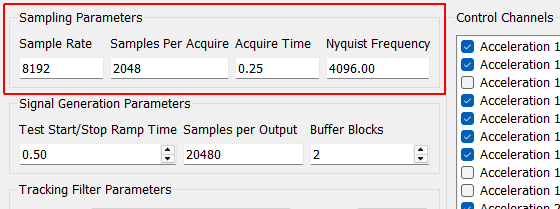
Sampling Parameters
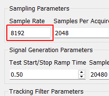
Sample Rate Sample rate in samples per second of the data acquisition hardware. This is a global parameter and must be set in the Data Acquisition Setup tab.
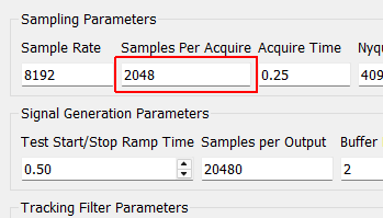
Samples Per Acquire Number of samples that the control process processes at a time. This is driven by the Rattlesnake read buffer size from the data acquisition parameters.
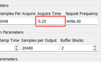
Acquire Time Time to acquire each acquisition chunk in seconds. This is the Samples per Acquire divided by the Sample Rate.
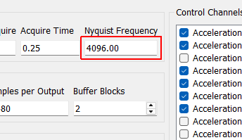
Nyquist Frequency The Nyquist Frequency is the highest frequency that can be analyzed using frequency domain techniques. It is the Sample Rate / 2.
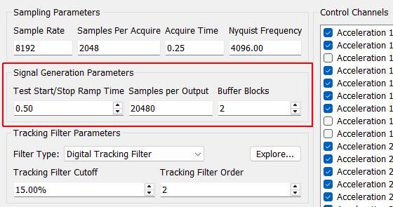
Signal Generation Parameters
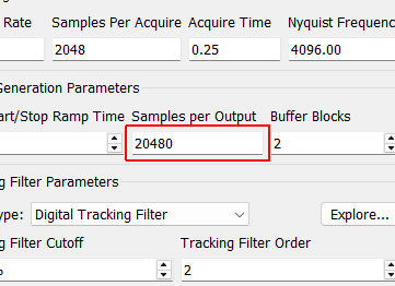
Samples per Output Number of new samples generated by each realization taking into account the overlap with the previous realization.
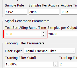
Test Start/Stop Ramp Time Time in seconds that the controller takes to change the test level to or from zero. The test level is changed smoothly to prevent damaging the excitation hardware or part under test. Larger numbers will result in a more smooth transition between test levels, while smaller numbers will make the test level change more quickly.
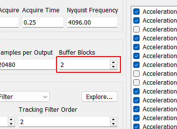
Buffer Blocks The number of blocks to keep in the signal generation buffer. A smaller number will make the controller more responsive but also increase the risk of underflow issues which will stop the test abruptly and may damage test hardware.
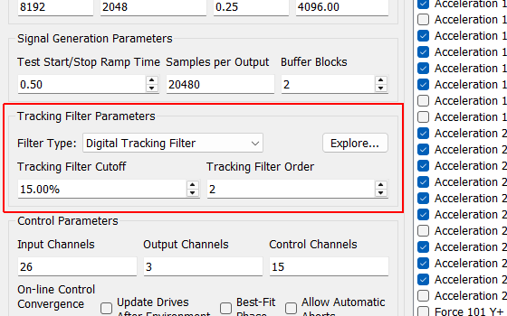
Tracking Filter Parameters
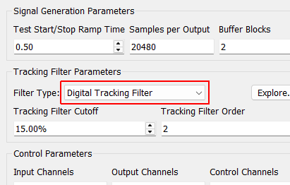
Filter Type The type of filter used to extract the sinusoidal components from the running time data. The Digital Tracking Filter is a less computationally intensive filter, but can struggle to reject noise, other environments, or multiple sine tones. The Overlapped Vold-Kalman filter will do a better job rejecting noise and other environments, and can seamlessly handle multiple overlapping sine tones if they are all defined in this environment. For large tests, the Overlapped Vold-Kalman filter may not be able to be run real-time, which can cause underflow issues as the controller is waiting for its next control decision. It is highly recommended that users use the Explore... button to carefully evaluate their filter parameters and computational complexity!
Explore... Bring up a dialog box allowing the user to explore filter settings for their given test. The user should have their specifications defined prior to clicking this button to ensure filter exploration is performed on the most realistic dataset.
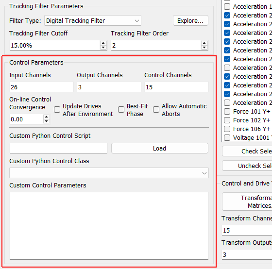
Control Parameters
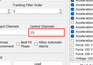
Control Channels A display showing the total number of physical channels this environment is controlling to.
Control Python Script Python script used to specify the control law.
Load Opens a file dialog to load in a Python script containing the control law.
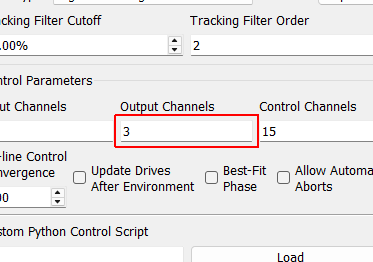
Output Channels A display showing the total number of physical channels this environment is outputting to excitation devices such as vibration shakers.
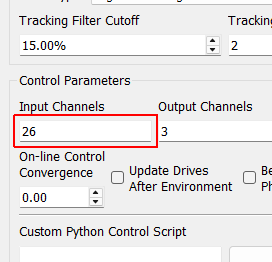
Input Channels A display showing the total number of physical channels this environment is measuring, including excitation channels and control channels.
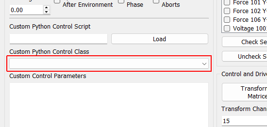
Control Python Class Selects the class in the Python script to use as the control law.
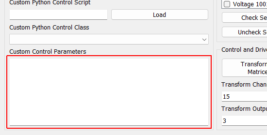
Custom Control Parameters Any additional parameters needed by the control law are entered in this text box. It is up to the control law to prescribe what is needed to be defined in this box. The data entered into this box will be passed to the control law as a string to the “extra_parameters” argument. Control laws should parse this string to extract needed information.
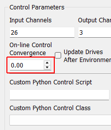
On-line Control Convergence A scale factor on the on-line closed loop control. Smaller values will make the controller converge more slowly but may increase stability.
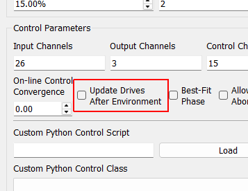
Update Drives After Environment If checked, the initial open-loop drive computation will be updated based on the control achieved during the previous run.
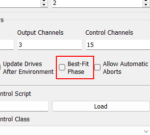
Best-Fit Phase If checked, the absolute phase information will not be controlled to, but rather only the relative phase information between channels. This can be useful if there are time synchronization issues between acquisition and output.
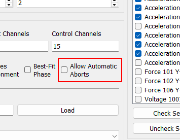
Allow Automatic Aborts If checked, the controller will abort if any abort threshold is reached.
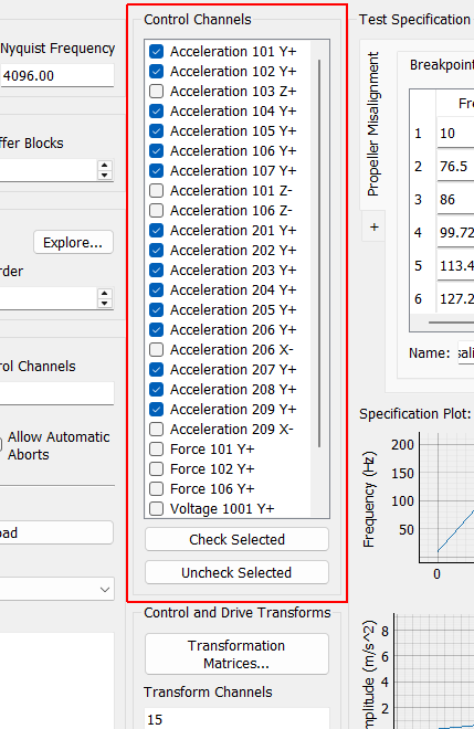
Control Channels
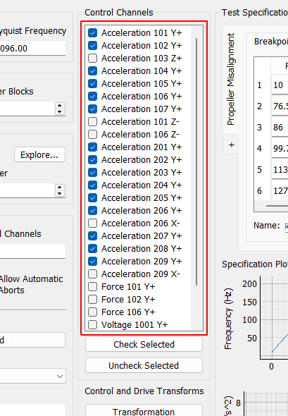
Control Channels Channels that are checked will be used as the control channels for this environment. The control channels should be ordered in the specification the same way they are ordered in this list.
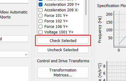
Check Selected When clicked, any selected channels in the Control Channels list will be checked, and therefore used as control channels in the environment.
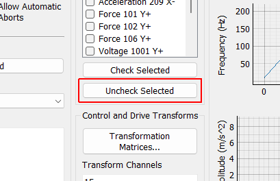
Uncheck Selected When clicked, any selected channels in the Control Channels list will be unchecked, and therefore not used as control channels in the environment.
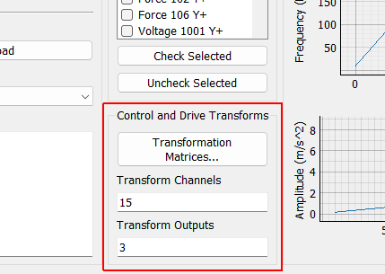
Control and Drive Transforms
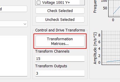
Transformation Matrices... Open the transformation matrix dialog to allow specification of transformations to virtual control or virtual excitation channels.
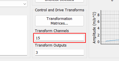
Transform Controls A display showing the number of virtual control channels in the environment due to transformation matrices applied to the physical control channels.
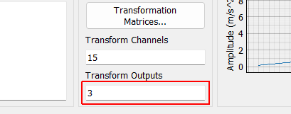
Transform Outputs A display showing the number of virtual excitation channels in the environment due to transformation matrices applied to the physical excitation channels.
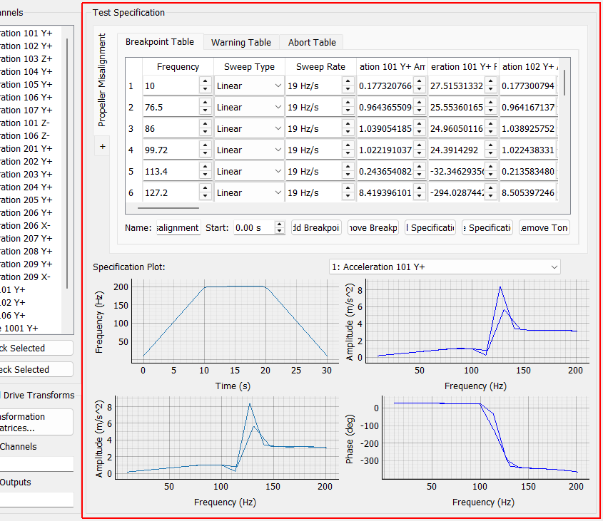
Test Specification
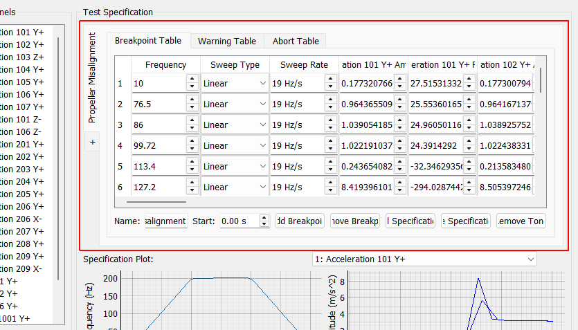
Specification Breakpoint Table Frequency breakpoints for the current environment. Use the Tabs to select currently defined sine tones. Clicking the (+) tab will create a new sine tone.
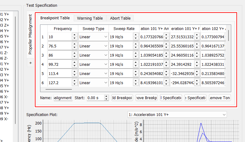
Table Selector Specify the control targets in the Breakpoint Table. Specify warning limits in the Warning Table. Specify abort thresholds in the Abort Table.
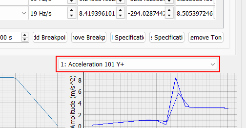
Control Channel Selector Select the control channel to visualize in the specification Amplitude and Phase plots.
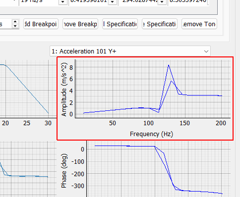
Specification Amplitude Plot The amplitude of the selected control degree of freedom and sine tone plotted against the frequency.
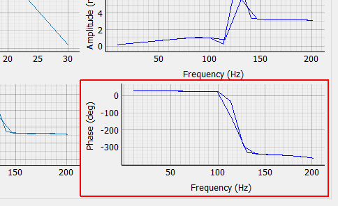
Specification Phase Plot The phase of the selected control degree of freedom and sine tone plotted against the frequency.
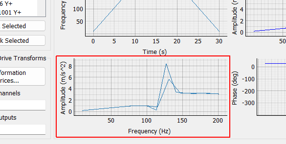
All Amplitudes Plot A plot showing all specified amplitudes against their frequencies.
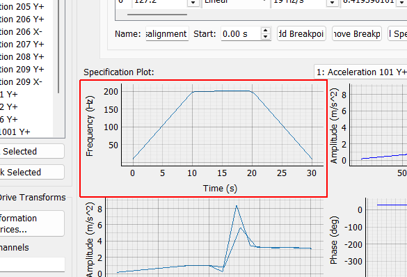
All Frequencies Plot A plot showing all sine tone frequencies defined in the specification over time.
Tracking Filter Cutoff A cutoff in percent of the nominal frequency to use in the digital tracking filter. This value allows the user to specify the trade-off between a faster filter with less noise rejection and a slower filter with more noise rejection.
Tracking Filter Order This value allows the user to specify the order of the filter used in the digital tracking filter.
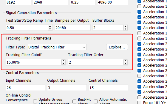
Tracking Filter Parameters

Tracking Filter Cutoff A cutoff in percent of the nominal frequency to use in the digital tracking filter. This value allows the user to specify the trade-off between a faster filter with less noise rejection and a slower filter with more noise rejection.
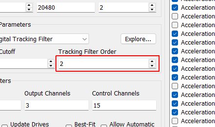
Tracking Filter Order This value allows the user to specify the order of the filter used in the digital tracking filter.
Vold-Kalman Filter Block Size The Vold-Kalman filter is meant to be run on entire signals and has start and end effects. To transform the Vold-Kalman filter into an on-line filter, an Overlap-and-Add strategy is utilized. This parameter specifies the size of the blocks of data analyzed by each pass of the Vold-Kalman filter.
Vold-Kalman Filter Bandwidth This parameter adjusts the pass-band of the Vold-Kalman filter, which allows the users to specify the trade-off between noise rejection and filter response time.
Vold-Kalman Filter Block Overlap The Vold-Kalman filter is meant to be run on entire signals and has start and end effects. To transform the Vold-Kalman filter into an on-line filter, an Overlap-and-Add strategy is utilized. This parameter specifies the overlap between subsequent measurement frames, aiming to remove the end effects of the filter.
Vold-Kalman Filter Order This value specifies the filter order of the Vold-Kalman filter, which modifies the filter response speed and computational complexity.
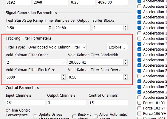
Tracking Filter Parameters
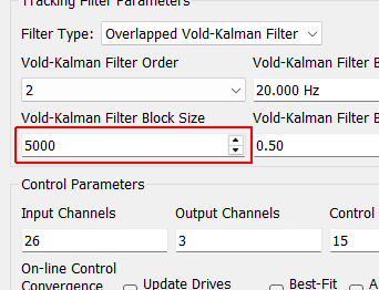
Vold-Kalman Filter Block Size The Vold-Kalman filter is meant to be run on entire signals and has start and end effects. To transform the Vold-Kalman filter into an on-line filter, an Overlap-and-Add strategy is utilized. This parameter specifies the size of the blocks of data analyzed by each pass of the Vold-Kalman filter.
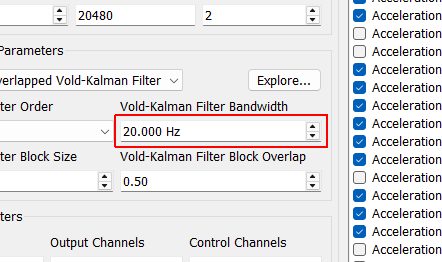
Vold-Kalman Filter Bandwidth This parameter adjusts the pass-band of the Vold-Kalman filter, which allows the users to specify the trade-off between noise rejection and filter response time.
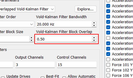
Vold-Kalman Filter Block Overlap The Vold-Kalman filter is meant to be run on entire signals and has start and end effects. To transform the Vold-Kalman filter into an on-line filter, an Overlap-and-Add strategy is utilized. This parameter specifies the overlap between subsequent measurement frames, aiming to remove the end effects of the filter.
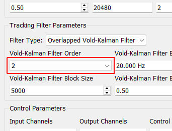
Vold-Kalman Filter Order This value specifies the filter order of the Vold-Kalman filter, which modifies the filter response speed and computational complexity.
Noise Level Simulate noise on the measurements to investigate noise rejection capabilities of the filter.
Plot Separate Frames If selected, the plots will show each frame of data as a separate color so end effects can be more easily identifier. If not selected, a single plot curve will be shown, which is more computationally efficient.
Compute Click this button to start the filter computation.
Full Time History Plot Shows the time history of the control channel including all sine tones in Blue and the sine tones extracted by the filter in Orange. If noise is applied, it is not shown on the desired (Blue) signal, but its effects will be shown on the extracted filter time history (Orange).
Order Time History Plot Shows the time history of the specified sine tone of the chosen control signal in Blue and the corresponding time signal identified by the specified filter parameters in Orange.
Sine Tone Amplitude Plot Plots the amplitude of the specification for the selected control channel and sine tone (Blue) compared to the amplitude extracted from the filtered time signal (Orange) for each frequency.
Sine Tone Phase Plot Plots the phase of the specification for the selected control channel and sine tone (Blue) compared to the phase extracted from the filtered time signal (Orange) for each frequency.
Channel Selector Select the control channel to apply the filter to.
Accept Accepts the specified filter parameters and puts their settings into the Environment Definition user interface.
Cancel Cancels the filter parameter selection and discards any changes made in this dialog box.
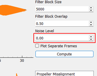
Noise Level Simulate noise on the measurements to investigate noise rejection capabilities of the filter.
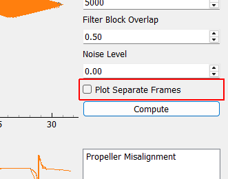
Plot Separate Frames If selected, the plots will show each frame of data as a separate color so end effects can be more easily identifier. If not selected, a single plot curve will be shown, which is more computationally efficient.
Compute Click this button to start the filter computation.
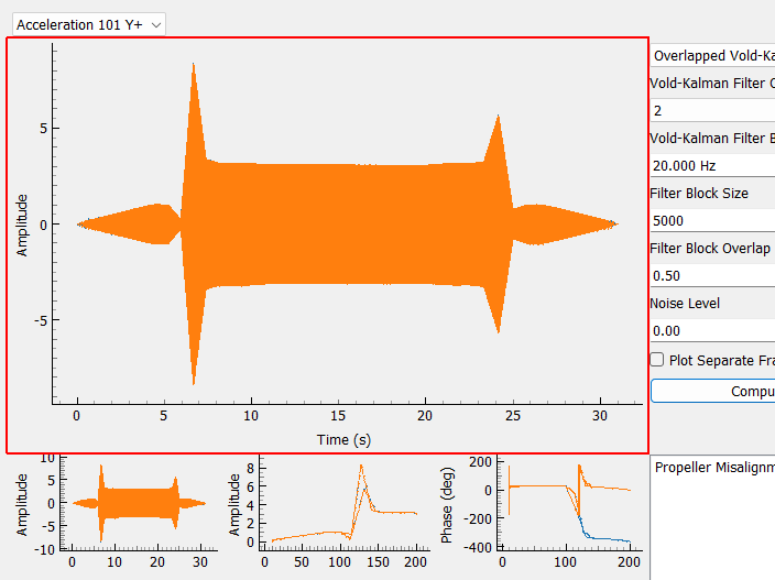
Full Time History Plot Shows the time history of the control channel including all sine tones in Blue and the sine tones extracted by the filter in Orange. If noise is applied, it is not shown on the desired (Blue) signal, but its effects will be shown on the extracted filter time history (Orange).
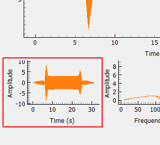
Order Time History Plot Shows the time history of the specified sine tone of the chosen control signal in Blue and the corresponding time signal identified by the specified filter parameters in Orange.
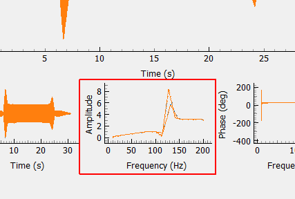
Sine Tone Amplitude Plot Plots the amplitude of the specification for the selected control channel and sine tone (Blue) compared to the amplitude extracted from the filtered time signal (Orange) for each frequency.
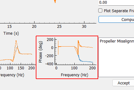
Sine Tone Phase Plot Plots the phase of the specification for the selected control channel and sine tone (Blue) compared to the phase extracted from the filtered time signal (Orange) for each frequency.
Channel Selector Select the control channel to apply the filter to.
Accept Accepts the specified filter parameters and puts their settings into the Environment Definition user interface.
Cancel Cancels the filter parameter selection and discards any changes made in this dialog box.
Breakpoint Table This table allows users to specify the frequency breakpoints for the selected sine tone in the environment. Sweep type and speed between the breakpoints can also be specified, as well as the amplitude and phase targets for each control channel at that breakpoint.
Add Breakpoint Adds a row to the breakpoint table, warning table, and abort tables.
Remove Breakpoint Removes the selected row from the breakpoint, warning, and abort tables.
Load Specification... Opens up a file dialog to load in a specification for this sine tone that was saved outside of Rattlesnake.
Remove Tone Removes this entire sine tone from the test specification.
Name The name used to reference this specific sine tone in the environment.
Start Used to specify the start time of this sine tone, allowing the different tones to start at different times.
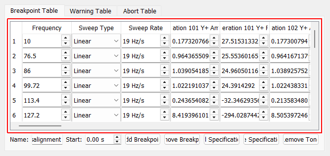
Breakpoint Table This table allows users to specify the frequency breakpoints for the selected sine tone in the environment. Sweep type and speed between the breakpoints can also be specified, as well as the amplitude and phase targets for each control channel at that breakpoint.
Add Breakpoint Adds a row to the breakpoint table, warning table, and abort tables.
Remove Breakpoint Removes the selected row from the breakpoint, warning, and abort tables.
Load Specification... Opens up a file dialog to load in a specification for this sine tone that was saved outside of Rattlesnake.
Remove Tone Removes this entire sine tone from the test specification.
Name The name used to reference this specific sine tone in the environment.
Start Used to specify the start time of this sine tone, allowing the different tones to start at different times.
Warning Table Define warning thresholds. For each breakpoint, both the warning ampiltude to the left of the breakpoint and to the right of the breakpoint can be specified. This allows users to, for example, set one level below a given breakpoint and a separate level above a given breakpoint.
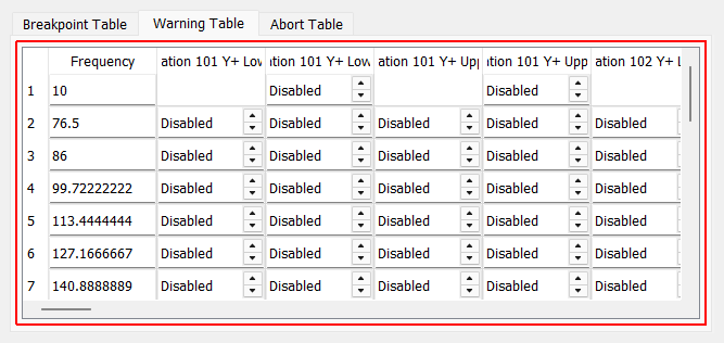
Warning Table Define warning thresholds. For each breakpoint, both the warning ampiltude to the left of the breakpoint and to the right of the breakpoint can be specified. This allows users to, for example, set one level below a given breakpoint and a separate level above a given breakpoint.
Abort Table Define abort thresholds. For each breakpoint, both the abort ampiltude to the left of the breakpoint and to the right of the breakpoint can be specified. This allows users to, for example, set one level below a given breakpoint and a separate level above a given breakpoint.
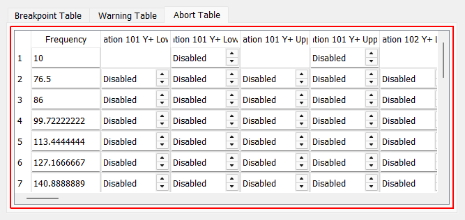
Abort Table Define abort thresholds. For each breakpoint, both the abort ampiltude to the left of the breakpoint and to the right of the breakpoint can be specified. This allows users to, for example, set one level below a given breakpoint and a separate level above a given breakpoint.