Theory for Miscellaneous Techniques#
ForceFinder has implemented some techniques that modify the sources but are not explicitly ISE methods and do not fit into a specific category. These miscellaneous techniques are described here for completeness of the theory documentation.
Buzz Method#
The buzz method, which is common in MIMO random vibration testing, is a technique for generating a square training response CPSD matrix from system ID data when only PSDs were provided as the training_response (the specification in a vibration test). This method is based on computing cross-power functions from the corresponding PSDs, coherence, and phase for the response and reference DOFs in the cross-power:
In this formulation, \(j\) is the response DOF for the cross-power, \(k\) is the reference DOF for the cross-power, \(G_{jj}\) and \(G_{kk}\) are the PSDs for the corresponding DOFs, and the phase and coherence is computed between the response and reference DOFs. The PSDs for this computation are extracted from the training_response for the SPR object and the phase and coherence is computed from the buzz_cpsd that was provided at object initialization.
Note
The buzz_cpsd is a square matrix where the response and reference DOFs are the training_response_coordinate for the SPR object.
In MIMO vibration testing, the buzz_cpsd will typically be computed from the system ID data that is collected prior to testing. However, the raw system ID data may not be available to generate buzz_cpsd in all cases. As an example, system ID data may not be available when performing pretest predictions using FRFs from a previous test or a finite element model. In these cases, buzz_cpsd can be generated from the training FRFs with the make_buzz_cpsd_from_frf method, which uses the following formulation:
Note
The buzz method has only been defined for CPSDs and is only implemented for the PowerSourcePathReceiver object by setting use_buzz kwarg in the inverse method to True.
Match Trace Updating#
The match trace technique is used to help correct for potential bias errors that are induced by the ISE method, where the average reconstructed_training_response is higher or lower than the training_response. This technique updates the source amplitudes with a factor that is computed by dividing the sum of the PSD amplitudes for the training_response by the sum of the PSD amplitudes for the reconstructed_training_response:
The sources are updated with the \(update\_factor\) with the following expression:
Note
Match trace updating has only been defined for CPSDs and is only implemented for the PowerSourcePathReceiver object with the match_trace_update method.
Tip
Match trace updating can lead to unexpected source amplitudes or errors in the reconstructed_training_response for specific DOFs. As such, practitioners should carefully inspect the test or simulation results when using match trace updating.
Reduce Drives Updating#
The reduce drives update was developed for situations in MIMO random vibration testing where the practitioner is satisfied with the dB error of the reconstructed_training_response compared to the training_response, but needs to reduce the drive voltage to be within the capabilities of the test system. As a general concept, the method computes the updated drives via the following constrained optimization:
Where the optimization is set-up so \(\begin{bmatrix}G_{ff}\end{bmatrix}\) is required to be hermitian. The \(upper\_bound\) and \(lower\_bound\) are defined by the dB error of the reconstructed_training_response PSDs, which is computed with:
The \({dB}_{error}\) is a frequency dependent quantity that is defined for each DOF in the training_response. The \(dB\_error\_ratio\) is an optional modifier for the error calculation, to allow for more or less error in the reconstructed_training_response after the reduce drives update.
Note
A \(db\_error\_ratio\) that is less than one is likely unfeasible in the reduce drives update, which could lead to a failed optimization.
The \(upper\_bound\) and \(lower\_bound\) are computed from the \({dB}_{error}\) with:
The drive minimization is computed not with a pure minimization on \(\begin{bmatrix}G_{ff}\end{bmatrix}\), rather it computes the minimization on the trace or infinity norm of \(\begin{bmatrix}G_{ff}\end{bmatrix}\), depending on whether the reduce_max_drive kwarg is set to false or true, respectively. Lastly, the optimization can be computed with a so-called “warm start”, where the initial guess for \(\begin{bmatrix}G_{ff}\end{bmatrix}\) is taken from the force attribute of the SPR object prior to the drive reduction. Otherwise, the initial guess for \(\begin{bmatrix}G_{ff}\end{bmatrix}\) is a matrix of zeros.
Tip
The constrained optimization for the reduce drives update may occasionally fail. It is recommended to review the error in the reconstructed_training_response compared to the training_response after the reduce drives update to ensure that the error after the update is acceptable.
Note
The reduce drives update has only been defined for CPSDs and is only implemented for the PowerSourcePathReceiver object with the reduce_drives_update method.
Transient Force Attenuation#
Transient force attenuation is used to limit the peak force amplitude (in the time domain) to a specified level. This technique is particularly useful for limiting the maximum drives in a transient MIMO vibration test (especially for shocks), so the drive voltage does not exceed the capabilities of the test system. It works by splitting the force attribute into segments, based on zero crossings, then scales any segments that exceeds the limit so they are within the desired range. The effects of the attenuation on the source time trace are shown in the figure below.
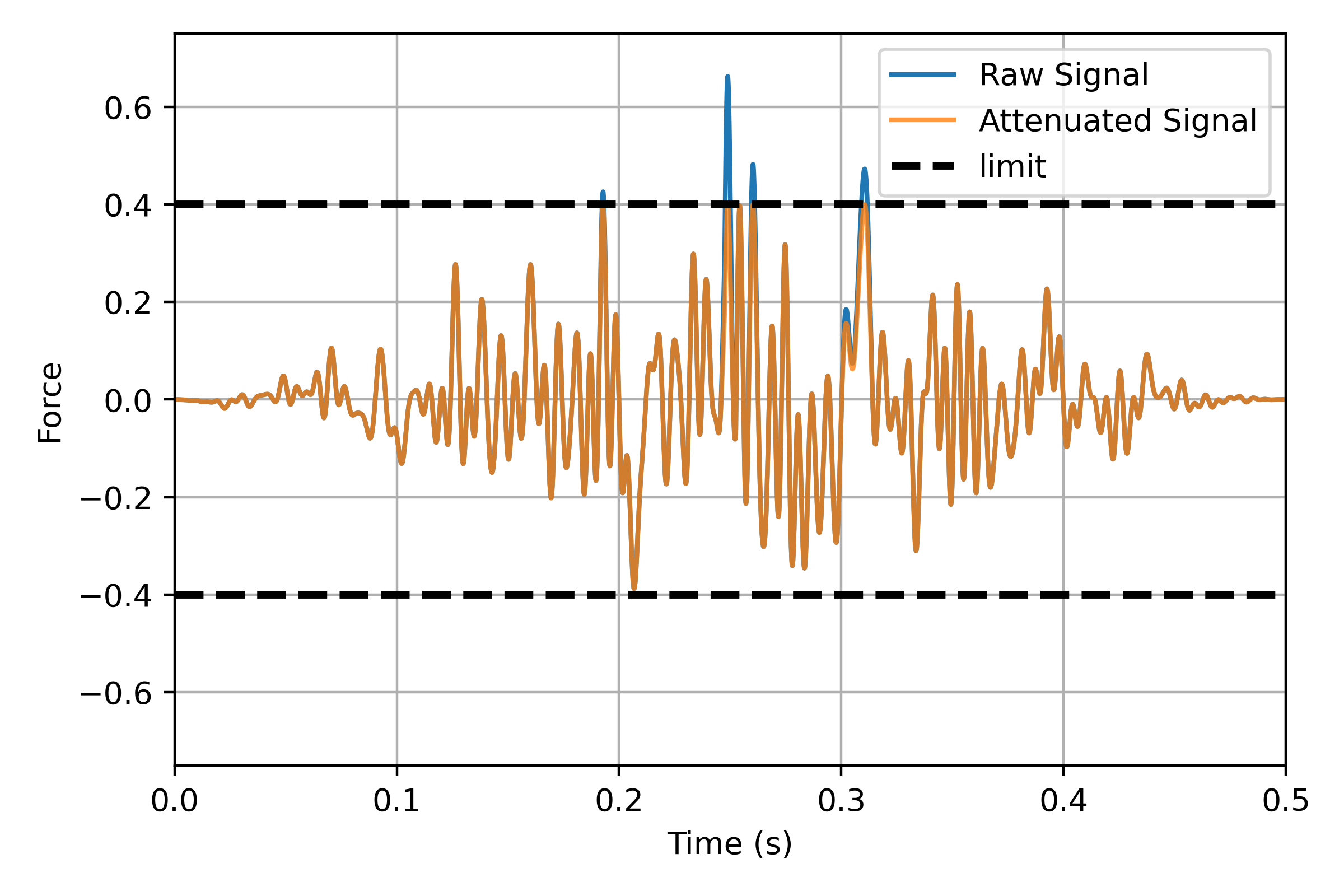
It can be seen that the attenuation primarily effects the peak amplitudes of the force and leaves the rest relatively unchanged. The only outlier to this general trend is the 0.3-0.315 s time range, where a large portion of the force segment is between zero crossings. This example demonstrates that whole segment of the force (between zero crossings) is scaled down, even though one of the peaks in that time range is well below the limit.
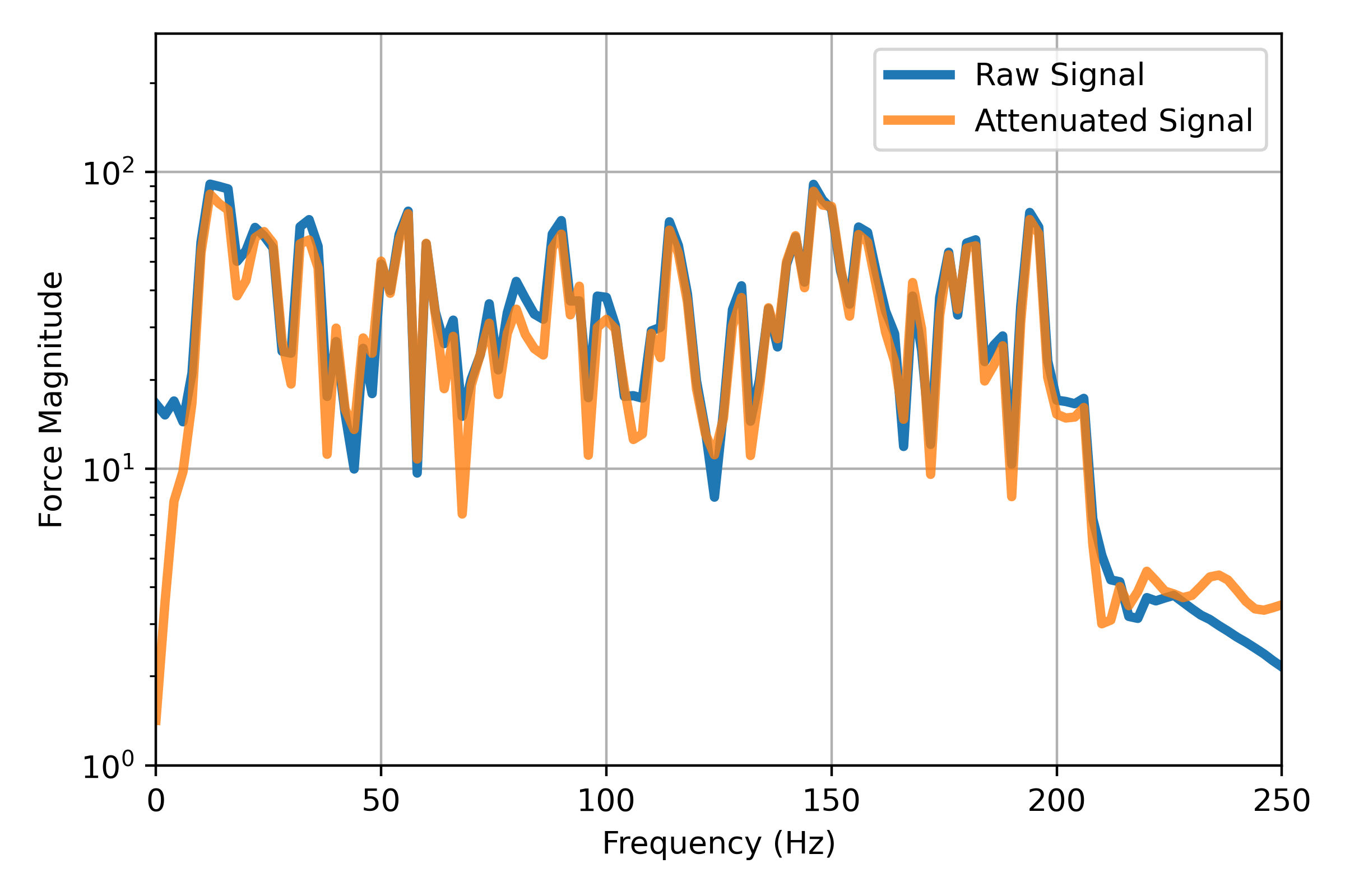
Further, the attenuation generally has minor effect on the frequency content of the force, since the shape and RMS level of the signal is not being dramatically changed. This is shown in the figure below, which shows the spectra of the raw and unattenuated time signals from the above plot.
Warning
The attenuation may have a more dramatic impact on the frequency content of the force, depending on the level of attenuation and the significance of the attenuated peak to the overall force. As such, it is suggested that the force and reconstructed_training_response be evaluated after the attenuation.
Note
The force attenuation has only been defined for time signals and is only implemented for the TransientSourcePathReceiver object with the attenuate_force method.
Response Limiting#
Response limiting is a common technique in vibration testing that is used to limit the vibration levels at DOFs that are not included in the training_response. The responses at these so-called “limit DOFs” are not directly controlled. Rather, the forces are modified to ensure that the levels at the limit DOFs do not exceed a specified limit.
Limits are commonly used in cases where it is inappropriate to define a training_response at a particular DOF (due to lack of data or other reasons), but there is sufficient engineering information to state that the vibration levels should not exceed a specified level. Examples where limits could be used include:
Limiting the vibration levels on a sensitive component (in a subassembly or system level test) to ensure that they do not exceed the levels that the component had previously been qualified to.
Limiting the strain or force levels in major structural elements, since the boundary condition mismatch between the vibration test and operating condition may lead to excessive and unrealistic loads on the system.
Response limiting has been implemented in ForceFinder for the PowerSourcePathReceiver with a scaling method that is similar to match trace updating. The \(update\_factor\) for the response limiting is computed with:
Where \(G_{xx}^{predicted}\) is the predicted_response PSD at the limit DOF and \(G_{xx}^{limit}\) is the limit specification as a PSD that has the same frequency resolution as the SPR object. The sources are updated with the \(update\_factor\) with the following expression:
Limits can be applied for multiple limit DOFs and multiple limits, via an iterative process (one iteration for each limit), where a new \(update\_factor\) and updated \(\begin{bmatrix}G_{ff}\end{bmatrix}\) is computed at each iteration.
Note
Response limiting has primarily been defined for single axis vibration testing and has not been formally defined for situations with multiple sources. This limiting strategy is one possible method, but has not been widely adopted by the vibration testing community.
Note
Response limiting has only been implemented for the PowerSourcePathReceiver object with the apply_response_limit method.