Sample Rate Sample rate in samples per second of the data acquisition hardware, for display only. This is a global parameter and must be set in the Data Acquisition Setup tab.
Samples per Frame Samples per measurement frame in the controller. The measurement frame is the “block” of data upon which the signal processing will be performed. This value will determine the window size. A larger value will result in more frequency lines in the FFT analysis. This need not correspond to the read or write size in the data acquisition system.
Samples per Acquire Number of samples that the control process processes at a time. This will be equal to the Samples per Frame * (1 - Overlap Percentage / 100). This need not correspond to the read or write size of the data acquisition system as the control process acquisition is buffered.
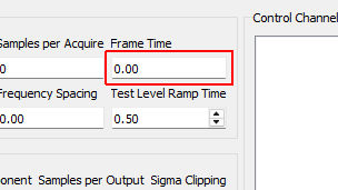
Frame Time Time to acquire each measurement frame in seconds. This is the Samples per Frame divided by the Sample Rate.
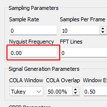
Nyquist Frequency The Nyquist Frequency is the highest frequency that can be analyzed using frequency domain techniques. It is the Sample Rate / 2.
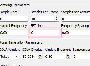
FFT Lines The number of frequency lines in the Fast Fourier Transform output, which is the number of frequency lines that will be in the Transfer Function and CPSD matrices.
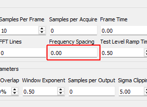
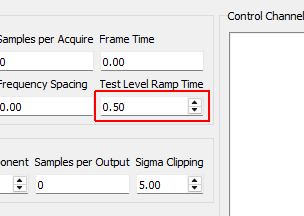
Frequency Spacing The frequency resolution of the measurement, computed by 1/Frame Time.
Test Level Ramp Time Time in seconds that the controller takes to change the test level. The test level is changed smoothly to prevent damaging the excitation hardware or part under test. Larger numbers will result in a more smooth transition between test levels, while smaller numbers will make the test level change more quickly.
COLA Window Window function to use when performing the Constant Overlap and Add to combine time realizations into a continuous signal. A Hann window is limited to 50% overlap. Tukey windows can have variable overlap.
COLA Overlap Percentage overlap between frames that are assembled using the Constant Overlap and Add
Window Exponent Exponent that the window function is raised to. This should typically be 0.5 to ensure a constant variance in the signal. Don’t change this value unless you know what you’re doing.
Samples per Output Number of new samples generated by each realization taking into account the overlap with the previous realization.
Sigma Clipping Number of standard deviations to include in the output signal. A value of 5 corresponds to effectively no clipping. A value of 3 is commonly used to reduce peak displacement. Setting this value too low will result in loss of dynamic range and non-gaussian output signals.
Frames in CPSD Number of measurement frames to use when computing CPSD matrices. Fewer frames will result in more responsive control. More frames will result in better averaging and noise rejection.
CPSD Window Window function to use when computing CPSDs.
CPSD Overlap Percentage overlap between measurements when constructing CPSDs.
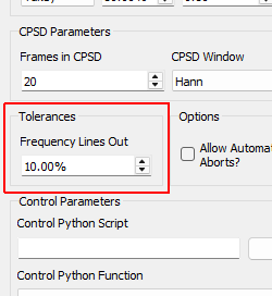
Frequency Lines Out Percentage of control frequency lines that can fall outside of limits before triggering warnings/aborts.
Allow Automatic Aborts? If checked, the controller will automatically abort if the abort level in the specification is hit.
Update Sys ID During Control? Checking this box will allow the controller to continually update the system identification to perhaps get a better control for nonlinear structures. Use with caution! If, for example, a shaker becomes disconnected, the controller will see the system identification between that shaker and the control channels become very small, and it will therefore try to push the shaker harder to make up for the poor transfer function, so the problem could explode.
Load Opens a file dialog to load in a Python script containing the control law.
Control Python Script Python script used to specify the control law.
Control Python Function Selects the function, generator function, or class in the Python script to use as the control law.
Control Type Select if the selected control law is a Function, Generator, Class, or Interactive Class. This should be detected automatically by inspection; users should not have to adjust this.
Control Parameters Any additional parameters needed by the control law are entered in this text box. It is up to the control law to prescribe what is needed to be defined in this box. The data entered into this box will be passed to the control law as a string to the “extra_parameters” argument. Control laws should parse this string to extract needed information.
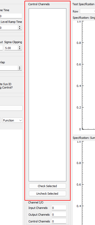
Control Channels Channels that are checked will be used as the control channels for this environment. The control channels should be ordered in the specification the same way they are ordered in this list. For example, the first row and column of the specification CPSD matrix will correspond to the first checked channel in this list.
Check Selected When clicked, any selected channels in the Control Channels list will be checked, and therefore used as control channels in the environment.
Uncheck Selected When clicked, any selected channels in the Control Channels list will be unchecked, and therefore not used as control channels in the environment.
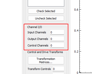
Input Channels A display showing the total number of physical channels this environment is measuring, including excitation channels and control channels.
Output Channels A display showing the total number of physical channels this environment is outputting to excitation devices such as vibration shakers.
Control Channels A display showing the total number of physical channels this environment is controlling to.
Transformation Matrices... Open the transformation matrix dialog to allow specification of transformations to virtual control or virtual excitation channels.
Transform Controls A display showing the number of virtual control channels in the environment due to transformation matrices applied to the physical control channels.
Transform Outputs A display showing the number of virtual excitation channels in the environment due to transformation matrices applied to the physical excitation channels.
Load Spec When clicked, opens a file dialog box to select a specification file to load.
Row Select the row of the CPSD matrix to visualize in the Specification: Single Entry plot.
Column Select the column of the CPSD matrix to visualize in the Specification: Single Entry plot.
Specification File Name File name of the loaded specification
Specification: Single Entry Displays a single entry in the specification CPSD matrix. If an off-diagonal value is selected, both real and imaginary parts will be shown. If warning and abort limits exist in the specification, these will also be shown.
Specification: Sum of ASDs Displays the trace (or sum of diagonals) of the CPSD matrix to give an overview of the frequency content in the specification.
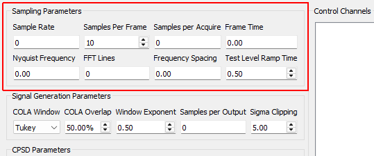
Sampling Parameters Settings
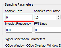
Sample Rate Sample rate in samples per second of the data acquisition hardware, for display only. This is a global parameter and must be set in the Data Acquisition Setup tab.
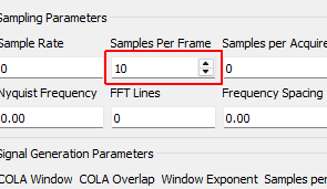
Samples per Frame Samples per measurement frame in the controller. The measurement frame is the “block” of data upon which the signal processing will be performed. This value will determine the window size. A larger value will result in more frequency lines in the FFT analysis. This need not correspond to the read or write size in the data acquisition system.
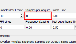
Samples per Acquire Number of samples that the control process processes at a time. This will be equal to the Samples per Frame * (1 - Overlap Percentage / 100). This need not correspond to the read or write size of the data acquisition system as the control process acquisition is buffered.
Frame Time Time to acquire each measurement frame in seconds. This is the Samples per Frame divided by the Sample Rate.
Nyquist Frequency The Nyquist Frequency is the highest frequency that can be analyzed using frequency domain techniques. It is the Sample Rate / 2.
FFT Lines The number of frequency lines in the Fast Fourier Transform output, which is the number of frequency lines that will be in the Transfer Function and CPSD matrices.
Frequency Spacing The frequency resolution of the measurement, computed by 1/Frame Time.
Test Level Ramp Time Time in seconds that the controller takes to change the test level. The test level is changed smoothly to prevent damaging the excitation hardware or part under test. Larger numbers will result in a more smooth transition between test levels, while smaller numbers will make the test level change more quickly.
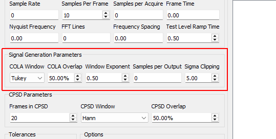
Signal Generation Parameters Settings
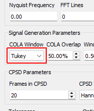
COLA Window Window function to use when performing the Constant Overlap and Add to combine time realizations into a continuous signal. A Hann window is limited to 50% overlap. Tukey windows can have variable overlap.
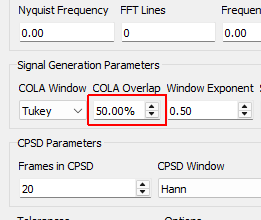
COLA Overlap Percentage overlap between frames that are assembled using the Constant Overlap and Add
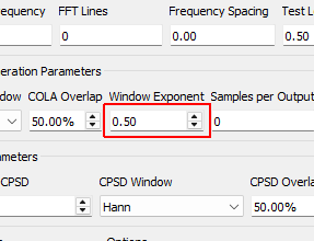
Window Exponent Exponent that the window function is raised to. This should typically be 0.5 to ensure a constant variance in the signal. Don’t change this value unless you know what you’re doing.
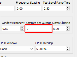
Samples per Output Number of new samples generated by each realization taking into account the overlap with the previous realization.
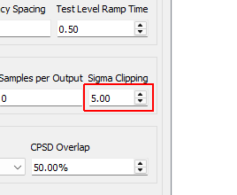
Sigma Clipping Number of standard deviations to include in the output signal. A value of 5 corresponds to effectively no clipping. A value of 3 is commonly used to reduce peak displacement. Setting this value too low will result in loss of dynamic range and non-gaussian output signals.
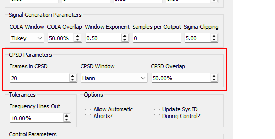
CPSD Parameters Settings
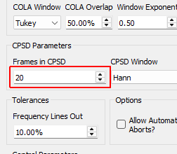
Frames in CPSD Number of measurement frames to use when computing CPSD matrices. Fewer frames will result in more responsive control. More frames will result in better averaging and noise rejection.
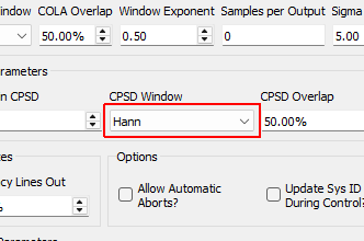
CPSD Window Window function to use when computing CPSDs.
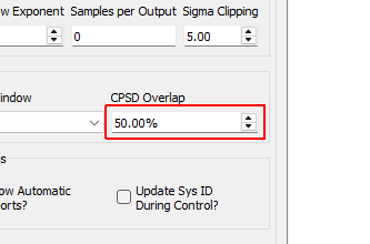
CPSD Overlap Percentage overlap between measurements when constructing CPSDs.
Tolerances Settings
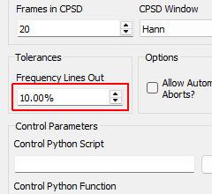
Frequency Lines Out Percentage of control frequency lines that can fall outside of limits before triggering warnings/aborts.
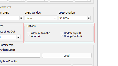
Options Settings
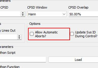
Allow Automatic Aborts? If checked, the controller will automatically abort if the abort level in the specification is hit.
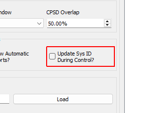
Update Sys ID During Control? Checking this box will allow the controller to continually update the system identification to perhaps get a better control for nonlinear structures. Use with caution! If, for example, a shaker becomes disconnected, the controller will see the system identification between that shaker and the control channels become very small, and it will therefore try to push the shaker harder to make up for the poor transfer function, so the problem could explode.
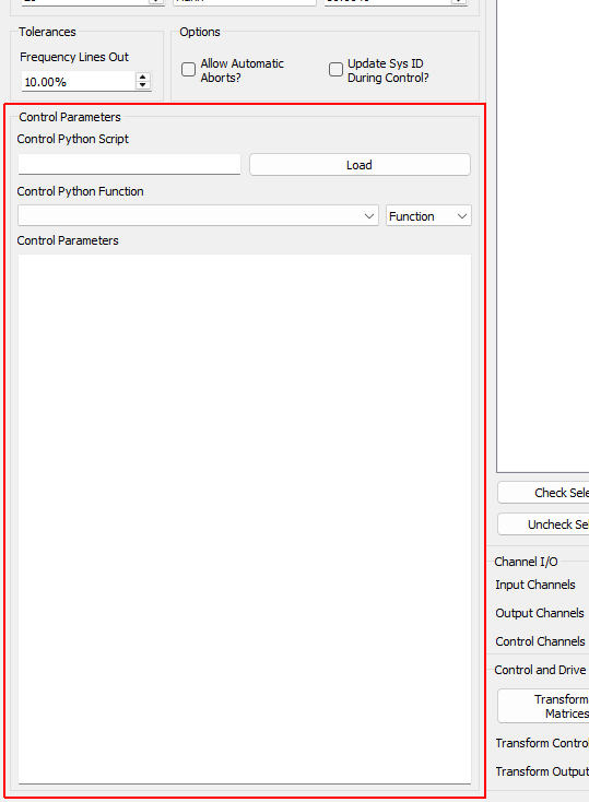
Control Parameters Settings
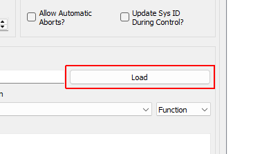
Load Opens a file dialog to load in a Python script containing the control law.
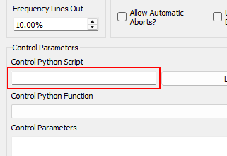
Control Python Script Python script used to specify the control law.
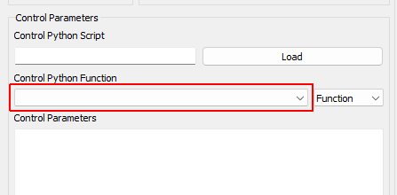
Control Python Function Selects the function, generator function, or class in the Python script to use as the control law.
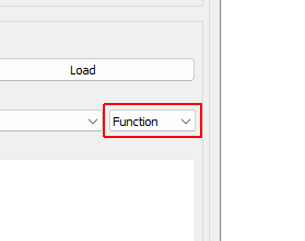
Control Type Select if the selected control law is a Function, Generator, Class, or Interactive Class. This should be detected automatically by inspection; users should not have to adjust this.
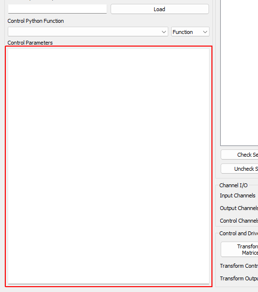
Control Parameters Any additional parameters needed by the control law are entered in this text box. It is up to the control law to prescribe what is needed to be defined in this box. The data entered into this box will be passed to the control law as a string to the “extra_parameters” argument. Control laws should parse this string to extract needed information.
Control Channels Settings
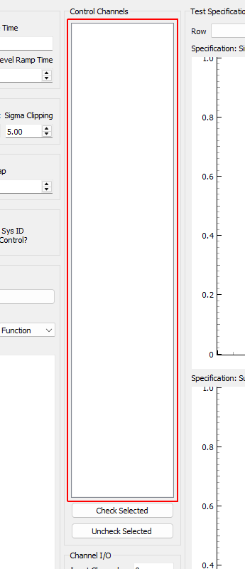
Control Channels Channels that are checked will be used as the control channels for this environment. The control channels should be ordered in the specification the same way they are ordered in this list. For example, the first row and column of the specification CPSD matrix will correspond to the first checked channel in this list.
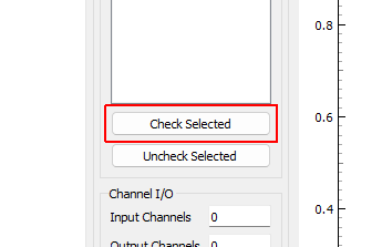
Check Selected When clicked, any selected channels in the Control Channels list will be checked, and therefore used as control channels in the environment.
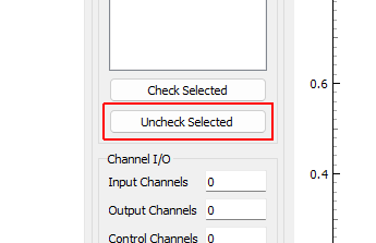
Uncheck Selected When clicked, any selected channels in the Control Channels list will be unchecked, and therefore not used as control channels in the environment.
Channel I/O Settings
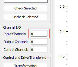
Input Channels A display showing the total number of physical channels this environment is measuring, including excitation channels and control channels.
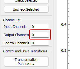
Output Channels A display showing the total number of physical channels this environment is outputting to excitation devices such as vibration shakers.
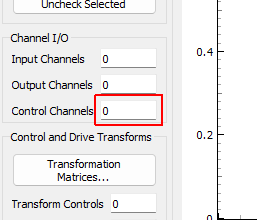
Control Channels A display showing the total number of physical channels this environment is controlling to.
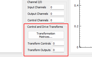
Control and Drive Transforms Settings
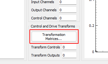
Transformation Matrices... Open the transformation matrix dialog to allow specification of transformations to virtual control or virtual excitation channels.
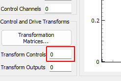
Transform Controls A display showing the number of virtual control channels in the environment due to transformation matrices applied to the physical control channels.
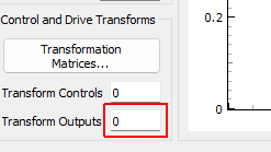
Transform Outputs A display showing the number of virtual excitation channels in the environment due to transformation matrices applied to the physical excitation channels.
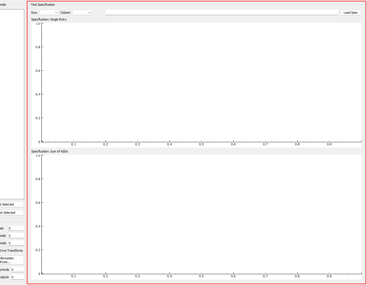
Test Specification Settings
Load Spec When clicked, opens a file dialog box to select a specification file to load.
Row Select the row of the CPSD matrix to visualize in the Specification: Single Entry plot.
Column Select the column of the CPSD matrix to visualize in the Specification: Single Entry plot.
Specification File Name File name of the loaded specification
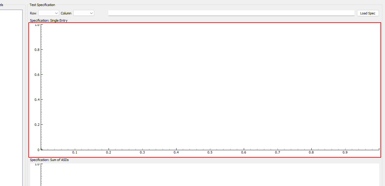
Specification: Single Entry Displays a single entry in the specification CPSD matrix. If an off-diagonal value is selected, both real and imaginary parts will be shown. If warning and abort limits exist in the specification, these will also be shown.
Specification: Sum of ASDs Displays the trace (or sum of diagonals) of the CPSD matrix to give an overview of the frequency content in the specification.