14Time History Generator
Rattlesnake’s Time History Generator environment provides the ability to simply stream a user-created signal to an output device. While this is a relatively simple environment, it can be used to create simple shocks or run open-loop excitation devices such as a centrifuge with voltage input being proportional to speed. There is no system identification, and therefore no test predictions that are made for this environment.
14.1Signal Definition
The first step to defining a Time History Generator environment is to create the signal that will be output. Rattlesnake accepts the signal in the form of a 2D array consisting of an output sample for each excitation signal for each time step. Signals can be loaded from Numpy *.npy or *.npz files or Matlab *.mat files. For *.npy files, the stored array defines the signal directly, and it is assumed that the signal uses the sample rate specified in Rattlesnake. Note that if a hardware device over-samples the output (e.g. LAN-XI, see Chapter 5), it is the over-sampled output sample rate that is used rather than the acquisition sample rate. Matlab *.mat and Numpy *.npz files allow the users to specify a time vector as well as a signal, and should contain the following data members:
signal A array containing the signal for each exciter for each time step in
t.t A array of times corresponding to the samples in the
signalmatrix.
where is the number of exciters and is the number of samples in the signal. If the time vector specified by t does not match the sample rate specified in Rattlesnake, the signal data will be linearly interpolated to provide the correct sample rate. If t is not provided in the *.mat or *.npz file, Rattlesnake will treat signal as if it were defined at the output sample rate of the controller.
The ordering of the signals in the signal file is the same as the ordering of the excitation devices in the channel table that are active in the current environment. The first signal will be played to the first excitation device, and so on.
Note that the environment will play the signal as-is, so it is up to the user to implement graceful startup and shutdown at the start and end of the signal if the test configuration requires it.
14.2Defining the Time History Generator Environment in Rattlesnake
In addition to the signal that will be played to the excitation devices, there is only one parameter that needs to be defined in the Time History Generator, which is the Cancel Rampdown Time. Several other displays exist for the user’s convenience. Figure 14.1 shows a Time History Generator sub-tab in the Environment Definition tab of Rattlesnake.
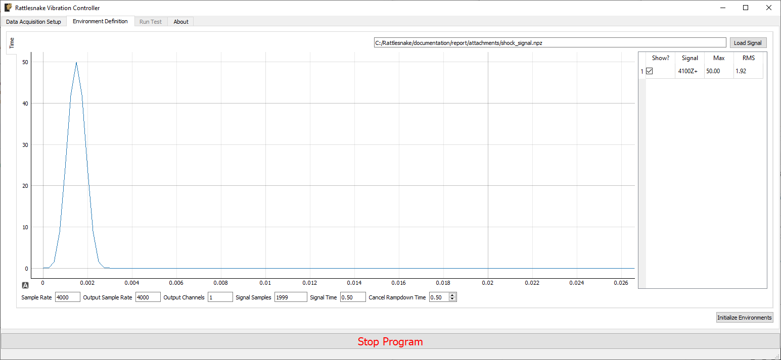
Figure 14.1:GUI defining the Time History Generation environment
Pressing the Load Signal button brings up a file dialog from which the signal file can be loaded. Once the file is loaded, it is displayed in the main plot window. Signal statistics are also displayed in the adjacent table. The checkbox in the Show? column of the table can be used to show or hide individual signals. The signal name in the Signal column is constructed from the node number and direction in the channel table. The Max and RMS value of the signal is also displayed.
Signal File File path from which the time signal was loaded.
Load Signal Opens a file dialog to select a file that contains time data to play to the shakers
Time History Plot A plot showing the loaded time signals. Individual signals can be displayed or hidden using the signal table.
Signal Table Lists the signals that will be played to the shakers in this environments. Signals can be hidden or displayed by checking the box in the Show? column.
At the bottom of the window, there are various computed parameters, and one user defined parameter.
Sample Rate The sample rate of the data acquistion. This is for display only; the sample rate is specified on the Data Acquisition Parameters tab.
Output Sample Rate The sample rate of the signal generator. This is for display only; the value is set on the Data Acquisition Tab. Depending on the type of data acquisition system used, this may be a parameter that can be changed independently, or it may be tied to the sample rate of the data acquisition system.
Output Channels Total number of output channels active in the environment.
Signal Samples Total number of samples in the loaded signal
Signal Time Total time it will take to generate the signal
Cancel Rampdown Time Time to ramp down the signal to zero if the environment is stopped manually before the signal ends.
14.3Running the Time History Generator Environment
The Time History Generator environment is then run on the Run Test tab of the controller. With the data acquisition system armed, the GUI looks like Figure 14.2.
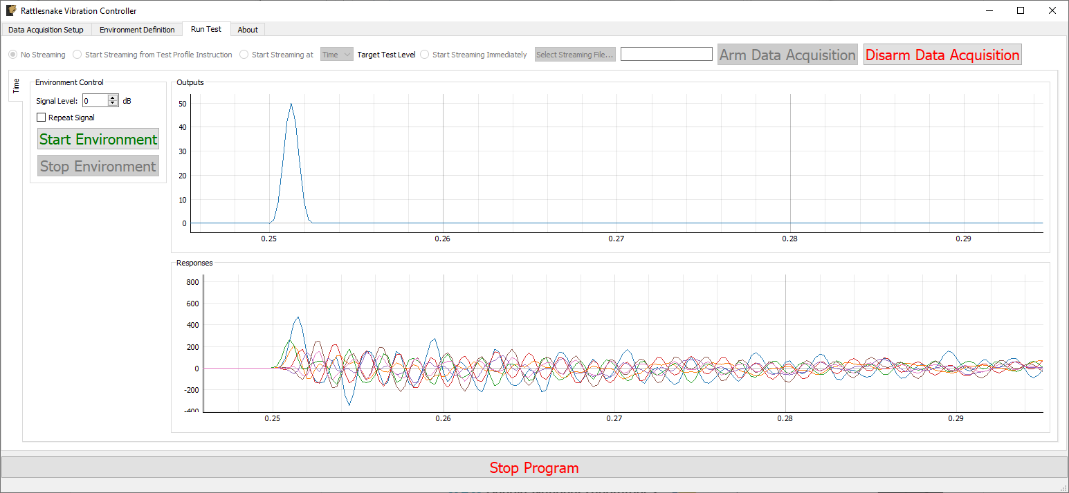
Figure 14.2:GUI for running the Time History Generator Environment
Two parameters can be defined prior to starting the environment.
Signal Level Scale factor in decibels applied to the signal.
Repeat Signal If checked, the signal will repeat continuously. If not checked, the environment will stop after the signal is played in its entirety.
Similar to other environments, there are Start Environment and Stop Environment buttons to control when the environment occurs. If the Stop Environment button is clicked, the signal will continue to play for the specified Cancel Rampdown Time while the environment ramps the signal level to zero.
Start Environment Starts playing the signal from the shakers and recording responses to that signal.
Stop Environment Stops the signal currently playing. It will ramp down the signal to zero over the time specified by the Cancel Rampdown Time parameter on the Environment Definition tab.
As the environment is running, data from both the output signals as well as any non-output signals active in the environment will be shown on the two plot windows.
Outputs Plot A plot of the output signals as they are measured.
Responses Plot A plot of the responses to the outputs that are being measured. Responses defined as any channel active in the environment that is not an output channel.
14.4Output NetCDF File Structure
When Rattlesnake saves data to a netCDF file, environment-specific parameters are stored in a netCDF group with the same name as the environment name. Similar to the root netCDF structure described in Section 3.8, this group will have its own attributes, dimensions, and variables, which are described here.
14.4.1NetCDF Dimensions
output_channels The number of output signals used by the environment
signal_samples The number of samples in the output signals
14.4.2NetCDF Attributes
cancel_rampdown_time The time to ramp to zero if the environment is stopped.
14.4.3NetCDF Variables
output_signal The signals that are played to the excitation devices Type: 64-bit float; Dimensions:
output_channelssignal_samples